Ah! You run the current through the bolt and nut! I understand now. Are you thinking of ever putting some more MOSFETs on in parallel?
I dont think it will ever be necessary to put 2 or more in parallel but you never know 
Here is the finished product, shrink wrapped and ready to be shipped out! Tested it on 24V and it worked well without any temp increase though I guess ill see how it works in the 52V 12S system it will be in.


3 Likes
Actually I’ve changed my mind completely lol. Yes I think there would be reason to put 2 or more fets in parallel for a higher current application, in fact im working on designing a PCB that is very similar to the original design, except it accommodates two TO-220 MOSFET’s instead of one for an upto ~60A system. I also may work on a schematic using the IRFS7530-7P which is pretty much the same fet that the VESC uses, because of its lower RDSON and lower C/W rating.
I mentioned in the post above about creating a board that would have two MOSFET’s in parallel, well I finished designing it and its obviously extremely similar to the original single fet design though it will work if you ever need to pull somewhere around 40-60A continuous. I also still plan on making a design around the IRFS7530-7P when I have time to do so.
.Zip with Brd and Schm files HERE
NEW IMAGE WITH SEPARATE RESISTORS FOR GATES:

4 Likes
Here is the IRFS7530-7P I was talking about. Obviously very similar to the other ones but it accommodates a D2PAK 7-P package MOSFET. Its not done yet I think theres some things I would change but yeah. And this would obviously have a strange mismatch of SMD and normal components, which would mean the fet would be on one side and everything else on the other. Also it took me a while to find a D2PAK lbr file for Eagle but HERE is the link to the Github file if your interested.
EDIT: UPDATED IMAGE

1 Like
I also made a schematic with 2 D2PAK MOSFET’s in it, cause why not. Below is an image of the 2x D2PAK schm and in the file there is the single D2PAK schm as well.
.Zip Download HERE
NEW IMAGE WITH SEPARATE RESISTORS FOR GATES:

1 Like
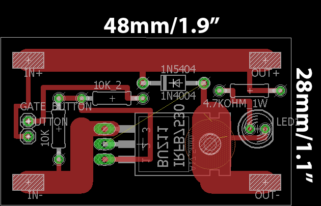
Managed to make the original switch WAY smaller, now it comes in at only 48mm x 28mm!
4 Likes
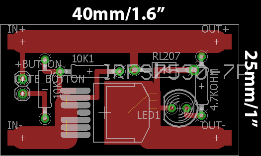
And obviously re-did the IRFB7530-7P board as well. And its even smaller than the previous one!
4 Likes
Why does it only handle about 30-60A ? The FET is rated to 295A. What do i am overlooking?
1 Like
Lol, so the max rating on a MOSFET is usually COMPLETE AND UDDER BULLSHIT. By that i mean like the TO-220 package leads will melt at around 75A so that’s out the window right there. And doing the math at 30A your going to see around a 94C degree temp rise on the 7530 which is fine but much higher and its gonna start to get sketchy. I heard that they literally COOL the IC’s in non conductive boiling liquid to test the max amperage, so yeah unless your planning on doing that, then don’t even worry about the supposed “max amperage” for the MOSFET, do the heat calc your self and figure out a safe operating amperage, or Google it and you’ll figure out the true max safe amperage.
I am just curious because the “Vedder Anti Spark Switch” is kinda standard but no one said that it is maxed to 60A… So the Vedder Switch cannot handle more than 60A? Somehow i doubt it but i am glad if somebody can enlighten me 
Well this Vedder Switch which is another great one and I highly recommend you take a look at, uses a 40A fuse on the positive rail which pretty much means, a 40A limit for the switch. I think it could possibly handle ~45A without a heat sink but I wouldn’t risk. And like I said just do the heat calculations because that is your main problem, heat generation and dissipation.
295A rating?? LOL did they get hobbyking to do their data sheets?
50A MAX
1 Like
Mhm… how much does a heatsink help? What else can i do to increase the amperage rate of the switch?
EDIT: i am a fool… yeah it can handle 50A max at 12S (or whatever voltage) so the rate is more than enough. Correct?
im fairly sure vedders switch uses 2 FETS so that makes a theoretical 100A max
Well yeah 50A would be definitely near its limit and it would be getting damn hot though I think it would work (haven’t done the equation, I’m tired.) anyways most EBoards don’t draw 50A continous so its not a big deal and if you did need to draw 50A cont, you’d be better off using 2 fet’s in parallel like my dual fet schematics. Also heatsinking does help a lot though its still not fixing your under lying problem of drawing to much current from your fet.
I just had a wrong calculation… The motor can pull up to 80A so i thought this switch wont work but i forget that the battery does not provide 12S @ 80A!
Thank you very much
1 Like
Yeah no problem. The motor can draw upwards of 100A+ on its first start up though that is for an extremely small amount of time and the switch could handle that perfectly.
1 Like
I am still confused somehow…
The battery provides 44,4V (12S) with a rather low amperage. Thus it will not melt the 40A fuse. Now i remembered that @hummie and @devin have measured some data:
This is the part where i get confused. The wattmeter is between the battery and the ESC so the amps peak should have blown a AntiSparkSwitch!?
It would be alright to setup the VESC battery max = <40A and the motor to 80A? It would be the same acceleration/torque if battery max is at 40A instead of 80A?
Thanks in advance for enlighten me!