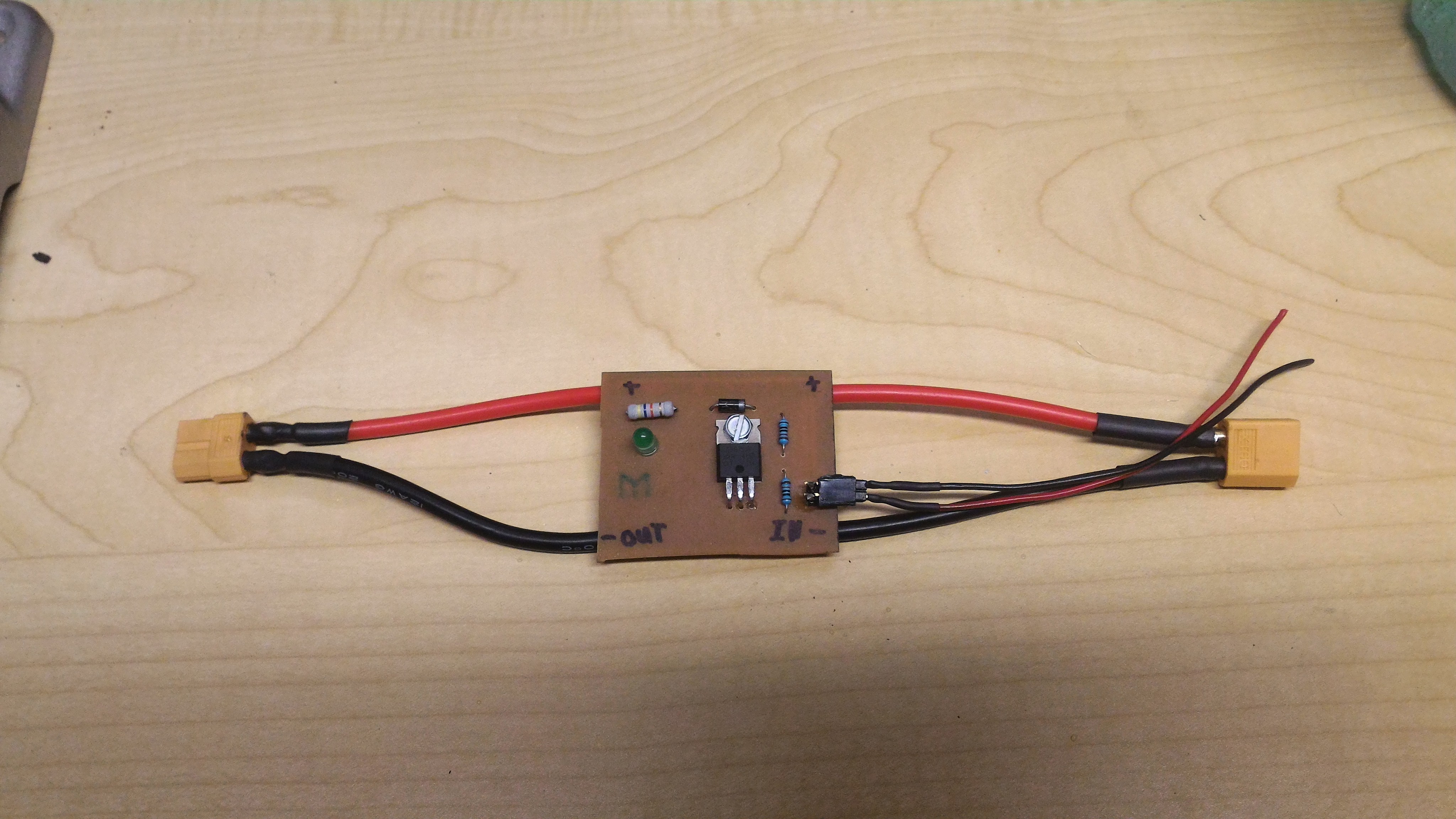
Hello everyone! This is my first post on eSk8 though ive been reading stuff on here for a while now. A couple months ago I wanted a new switch for my board other than my crap-a-tronic fuse switch that was falling apart. So I looked some up and saw a couple very similar devices online from Alien Drive, DIY Boards and a couple other sellers. They were all around $60 and I didn’t want to spend that much so I decided to build my own. I looked around a bit online and asked some questions on some forums and got some answers eventually. Currently the switch is built around a IRLB3034 N-Channel MOSFET which is an amazing fet because of its extremely low RDS of only 1.7m Ohm, which in turn makes it extremely efficient and cool running. I tested the switch on my board which draws around 8-10 Amps cruising normally and ~15 Amps going pretty fast. At any of these speeds the mosfet didnt even get warm, and I was testing this on a 90f degree day. The 3034 fet is great and super cheap, but the problem is it has a max voltage of 40V which will only work with 8S lipos at the most, though dont fret because I found a higher voltage mosfet! The IRFB7530 is another great fet with a rds of only 1.65mOhms and has a max voltage of 60V which means it can work with upto 12S LiPos. Anyways enough with the specs, I am going to upload the schematic for anyone who wants to build there own, but for people who dont want to build one themselves, I would be happy to make and sell them. The circuit would have its own custom PCB and ports for the switch to turn the fet on and off as well as XT60 connectors for power. If anyone is interested in buying one or getting some more info on it im more than happy to help! The couple of pics of the actual circuit was the very first version I made and if I were to do it again it would look far better.
HERE is where I purchased the IRLB3034 MOSFET’s. The rest of the components you should be able to source your self. I bought everything else on eBay FYI
Prices:IRFB7530 ~40A Single FET Switch ~$25IRFB7530 ~80A Dual FET Switch ~$35IRFB7530-7P ~100A Dual FET Switch ~$40IRFB7530-7P ~50A Single FET Switch ~$30FYI I custom make every PCB so if you need it to fit a certain size requirement just ask and ill try to accommodate it to your needs.
@JdogAwesome Thanks for sharing this! If you produced a parts list or BOM, that would be a huge help for anyone interested in building your design. If it was a list with links to a vendor like Mouser, that would be even better.
Yeah ill definitely do that. Personally I just bought the mosfet on EBay, though I had to order like 5 of them, though it was still only like under $10. Then there’s the diode which ill link, you can get those on eBay in small bulk packs for like $1-2 and there great to have for any electronics enthusiast. And then just some 10K resistors and perf board to assemble it on, though I would highly recommend just making your own PCB, its actually quite simple and looks beatiful!
Sorry for the extremely late reply I thought I sent this message already! Anyways here us what I meant to send to you:
No there is 0 spark because your arent connecting any wires with this, it is all controlled internally inside of the MOSFET.
!!!VERY IMPORTANT NOTICE!!!
Please read post number 67 about the gate resistor values!
Also I found this MOSFET, its the IRFP7718PBF and its capable of handling 75V or a 17S LiPo Pack! So if anyone was planning on making a 17S pack, then yeah I guess you could do that, though good luck finding an ESC capable of running 75V.
Here is a schematic I designed for the switch, in the example it uses an IRFB7530 mosfet, and is designed for 12S, though you can change that out for a different kind of mosfet. The circuit image and and .Zip download are below. Note that the LED resistor must be at least a 1/2W resistor but I would recommend a 1W so it doesn’t get to hot. IMPORTANT! The thick traces for the + and - rails are not thick enough to handle high amperage, you have to add a layer of solder on the top or a wire that runs along it to handle the higher amperage.
Hey ndwallick the diode is an essential part of the circuit. The diode lets buildup current flow from the - to the + lead which is the opposite of the way current normally flows, this is because of an electron buildup that can occur and destroy a circuit if a diode is not there to let the electrons flow back. Anyways, its a very important part of the circuit and if you were asking to see whether or not you need the diode, the answer is a definite yes, lol. Though thank you for asking the question so now others will know!
Hello Maxid, at the time of me needing a new switch for my EBoard, I had no idea the Vedder switch even existed, if I had I would have most likely used that design. When I created this thread I still had no idea the Vedder switch existed and it was only until someone told me about the Vedder switch because of how similar my switch is and the Vedder one were that I found about it. I still think that it cant hurt having more than one design for a MOSFET switch out there and this is my version of it, I know this one is very similar but still I don’t think it can do anybody any harm having this one out there.
Your through-hole components have the traces on the top of the board. I believe that you need to either flip the components, or flip the traces (make them blue).
That’s a good point but if you noticed how I’m using the heatsink flange for the mosfets drain, I have to have the components on the top side with the traces on the top side as well. Though you could definitely have just the mosfet on the top side and the other things like resistors and the diode on the bottom side.
Yeah that github link is kinda confusing but below is the real post on endles sphere about the switch. I highly recommend you take a look at both of these designs and just use whatever works better for you, or you like more.
Thread: https://endless-sphere.com/forums/viewtopic.php?f=31&t=73800
Yes, but literally all of your other components need to be on the other side of the board then, especially your LED and pin header, which you won’t be able to solder on (unless your via is already made there).