Sent out drawings today for quotes to manufacture…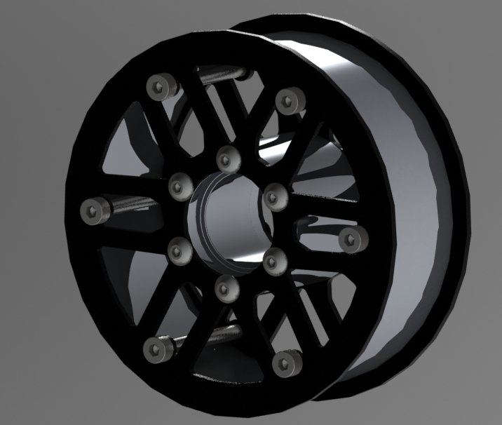
6 Likes
Looks great and maybe stronger than the earlier design, kudos
I read here on the forum that some say chain drive has better ground clearance… But according to a roller chain sprocket’s geometery it’s actually worse than ‘n belt drive system for a constand gearing ratio. Say for instance I want a 1:5 drivetrain ratio with an M5 pully system one can easily achieve it with a quite standard and common 66:13T selection. But with a roller chain sprocket the smallest motor sprocket on a 05B chain and bore Ø10 is 9T (one gets smaller but bore becomes a problem and 04B chain seems to ne weak). Now to have a ratio of 1:5 the driven sprocket needs to be 45T this sprocket has a OD of 118mm compared to the pully’s Ø105mm. That is 7mm less ground clearance for the roller chain drive system… Wanted to use chain for its advantages with robustness, but it seems to be more impractical.


5 Likes
Got Quotes back seems a wheel could be manufactured for $15 US. I’m okay with that.
1 Like
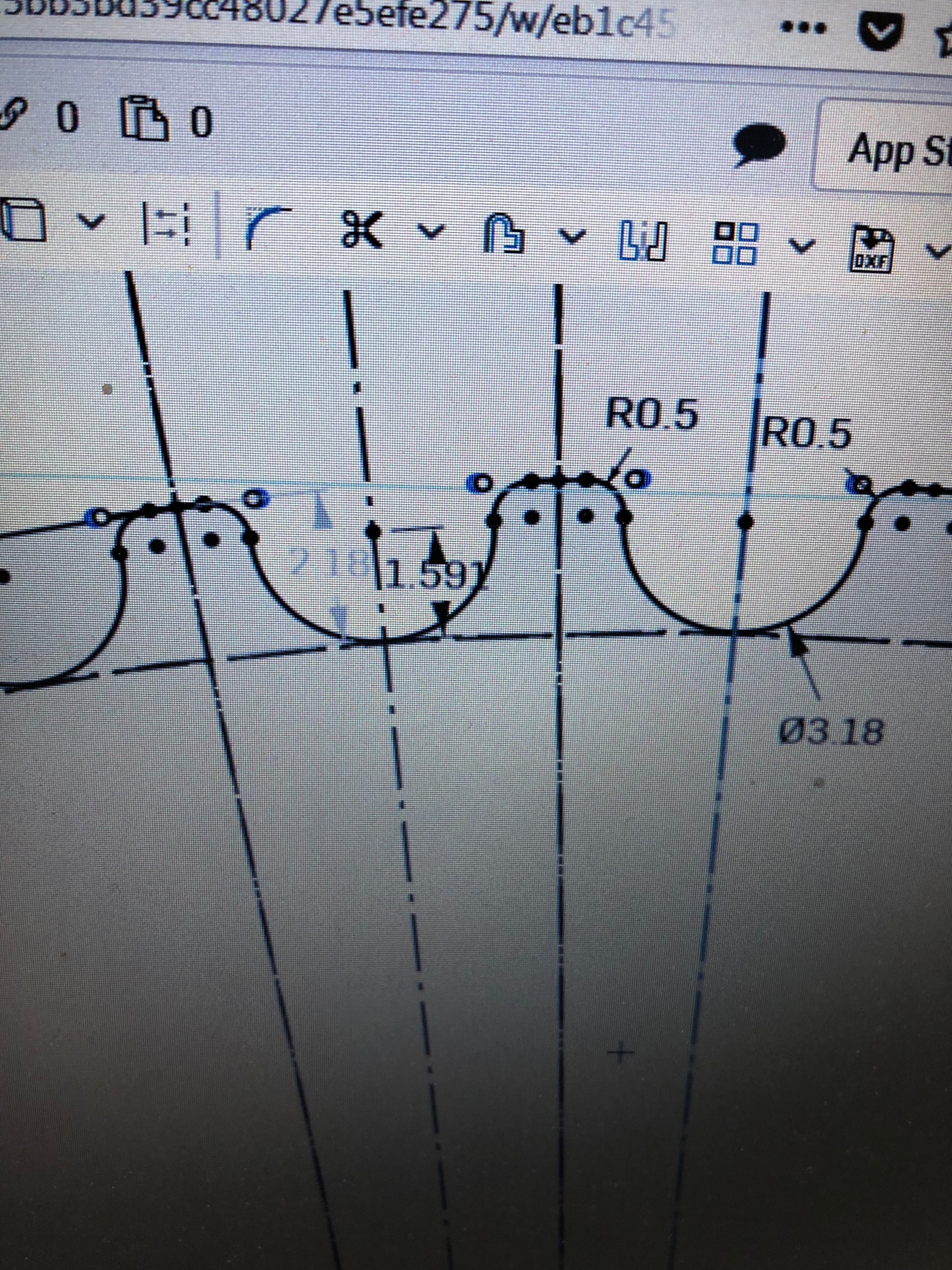
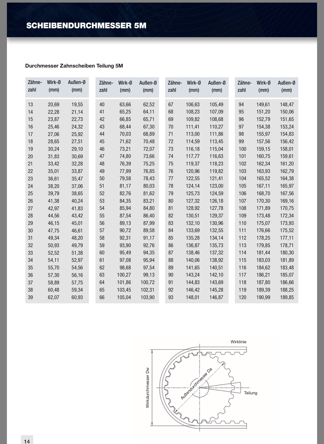
#Dimension HTD Pulley
I struggled so hard to find relatively proper documentaion regarding HTD pulley dimensions, all other information was only related to the belts itself and one needed to derive or guess dimensions. Here is an image link below.

For htd5m pulleys I used this values, which came out pretty well so far
1 Like
Thanks. I like your values it seems more sensible than using belt dimensions. Do you cut your own pulleys?
1 Like
Not really. Wouldn’t know how to fix the cut ends together. If you need a belt length calculator, you can use this. Works well as min for the most common teeth counts. https://www.bbman.com/belt-length-calculator/
Hehehehe… not cutting the belts I meen cutting (like in CNC cutting) the pulleys.
1 Like

 …read it too fast
I would be very happy if I would have my own cnc, but unfortunately I don’t have.
I printed already some in petg with this measurements and it worked out very well for me.
…read it too fast
I would be very happy if I would have my own cnc, but unfortunately I don’t have.
I printed already some in petg with this measurements and it worked out very well for me.
1 Like
Waiting for wheel assembly from suppliers… had loads of busy or public holidays in the last few weeks. In the mean time I designed a Scotts damper base plate mounting.


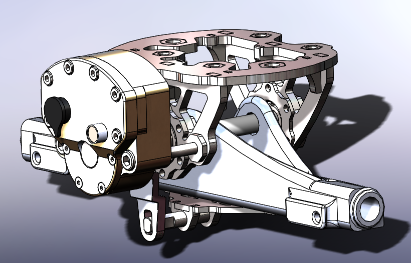
9 Likes
Man that’s a slick design. I really like how it avoid a heim joint
Seems like it may work with MBS and maybe others baseplates, interested in how it works out for you
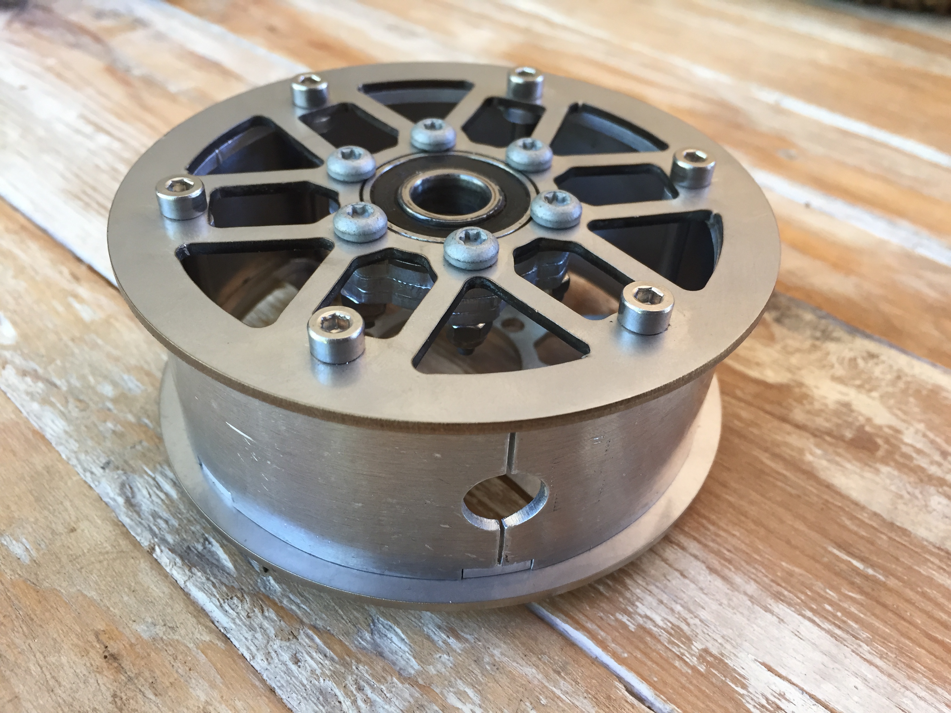
Lightly assembled the prototype hub and base plate. Will weld it probably next week, as parts fit quite sweet. Need to reduce the hub diameter to 91.5mm as it is a bitch assembling it.


7 Likes
Always great to see some updates on your project 
 looks dope!
2 Likes
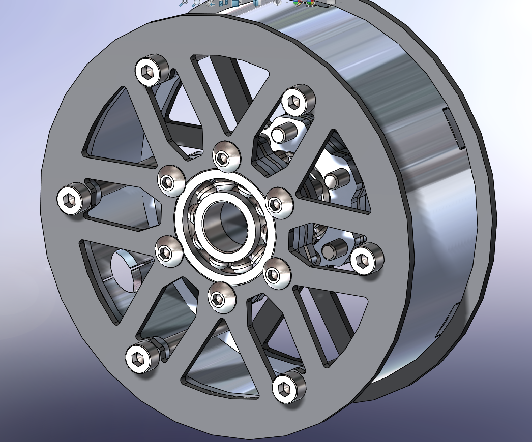
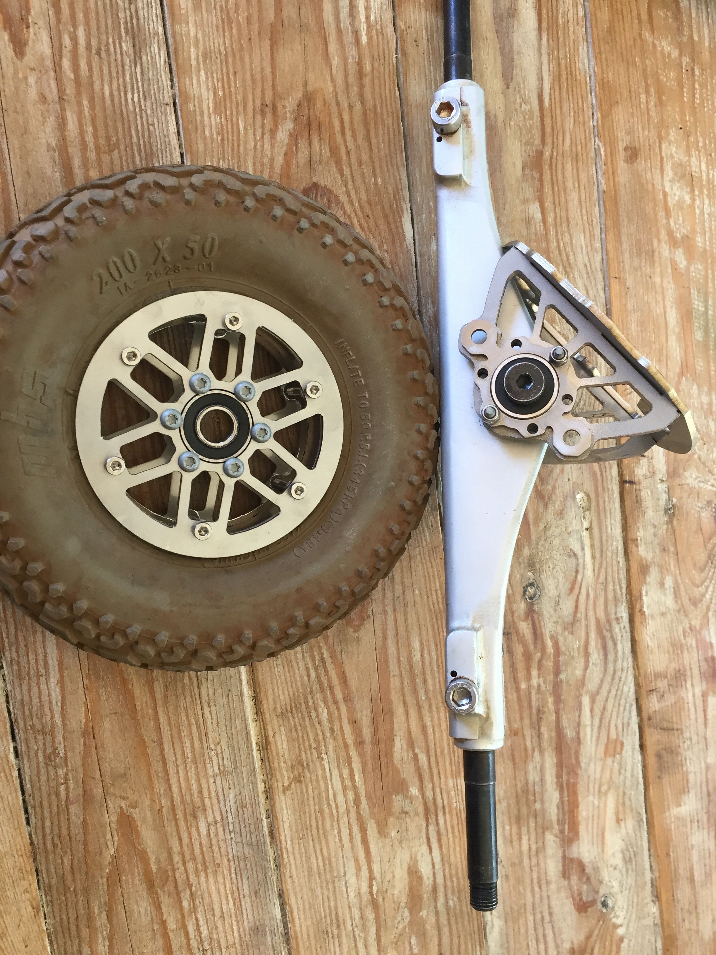
 I’m really impressed with how this wheel came out. The diameter of the bearing holes were specked at Ø28.05mm to have a proper bearing fit. It worked beautifully, a nice snug fit. The rim run true as gyro.
9 Likes
Looks good too
Hi Toby, Thanks, Pulleys HTD05 I’m okay with… it’s the chain sprockets haunting me.
I forgot about the sprockets inside SolidWorks’ toolbox…  So I used that and adjusted the tooth profile a bit too mesh better and have less chain slap (sprocket against the rollers during meshing), thus less noise. The drive sprocket is locally available of the shelf for something like 3USD and it could be quench hardened. It will be ISO 05B, 9T and the slave sprocket will be 42T, this one will be lasercut. Would have liked to have a better or larger reduction ratio but with the chain systems it is not possible unless one sacrifices ground clearance.


Think I’ll turn the Scotts damper arround… the front looks like some kind of robot face. Hahahaha!
4 Likes
awesome work and render bro
Are you also using a stearing-damper on the rear?
Thanks. I designed it to be on the front, don’t really know where would be best.