Can I ride it? Ill sign a release form 

Can I ride it? Ill sign a release form
Bet I could get around 90-100 with my regular slow speed…(15-20mph avg, 90-95ish pounds, 5ft…) 
You know, I just found out someone ate it during the first raptor 2 tour In sf be ause a truck broke haha
To reduce speed wobble: #1 speed wobbles are caused by the rear end steering. In cars the rear end doesn’t steer so they never get wobbles. Solution: have much stiffer suspension at the rear than at the front, this will force the board to steer with the front more than the rear, hence making it much more stable at speed. Because if you ever tried pushing a grocery cart backwards, you notice how hard it is to steer because when the rear end steers its much more sensitive than when the front end steers. I tighten up my rear trucks more than the front and never worry about speed wobbles. #2 maybe use longer wheelbase than any regular longboard to help with high speed stability? There’s a reason why hyper cars are almost as long as pickup trucks #3 tight as heck suspension. Why do sports cars have stiffer swaybars? Less bodyroll. Which makes them stable at high speed and at cornering.
Use the 3 points I mentioned and you could probably get away with going 100kph using a really long deck and regular reverse kingpin trucks that are concrete tight at the rear and almost as tight at the front.
I’m just a car mechanic, have been building and tuning my own cars. Also I’m into electric skateboards recently. This is just my 2 cents.
ESC is sorted out good enough for me, new mosfet drivers helped, nothing blows up. With my big motors it will run BLDC or FOC sensored. It wont run unsensored under 10 amps, too much noise in current sense for that. Got a hold of company that makes wind turbines and has motor simulation software. I will try to persuade them to simulate my motor and figure optimal magnet-stator spacing, before i waste more magnets. Slow progress due to too much IRL problems. Cheers!
If you have time play with this
Has a few days of free trial
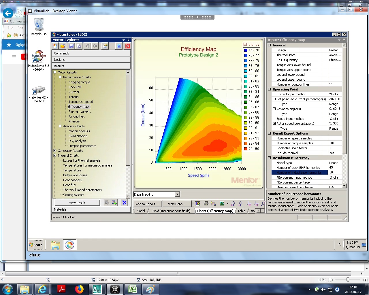
I have tested several configurations using this software in trial mode and here is result: problem was not with rotor-stator spacing but with spacing between magnets. Too much flux was “taken away” and formed closed loop between magnets without going into the stator. When magnet count is reduced to 34 and winding scheme is different motor produces designed parameters - 60 nm at 350A, peak stator flux 2,2T - just at steel core saturation point (at peak current). Spacing between magnets is increased form 0,25mm to 2,0mm. Total motor efficiency chart varies between 82% (at low RPM or low torque) to 96% in central region. Winding 2 turns delta or 1 turn wye. Now proceeding to manufacturing test piece.
Simulation results of existing configuration (42N36P) were within 3% of measured values from last test piece so i am certain simulation is accurate.
Cheers!
With saturation starting at 1.6t and 2.2t being maybe the max possible flux strength of electrical steel I guess ur going for the peak possible output regardless of efficiency then. Where will u even find a load big enough to get to such current? I feel we’d need to strap u down and send u up the steepest thing possible.
Nice, and with 42N36P you have a better winding factor of 0.966
How do you arrived at this conclusion? Just looking at the flux lines diagrams? Good find, maybe other hub motors also suffer from this since most have the magnets touching
And could you post the results of the final design? Mainly the rpmx(torque/efficiency/current/loss) diagram for it?
And a Hummie said, the flux is a bit high, but since you will probably never run at the peak for more than a few seconds its all good
Flux density reaches 2,2T at max current of 350A. It is under 1,5T when current does not exceed 250A. I made simulations for different values of current. So for normal riding no saturation and very high efficiency, at peak power i am going for highest torque and flux possible, slightly disregarding efficiency, however still somewhere above any ready-made motor. Value of 96% efficiency is present at 60% of max rpm and 30-50% of torque (going at 100 kph continous). I agree that with 42N36P winding factor was slightly better but with 34N36P it is 0,9525 and i get a lot less cogging (0,15 Nm peak 0,07Nm average), which means less noise and smoother ride. Right now i am just happy to fnally pinpoint the problem and find solution. All components i have are correct and can be used to get result.
I got to the solution by simulating over 20 motor configurations with different airgap and magnet count. 38 magnets go with same winding scheme but not nearly as good. Airgap is about 0,8mm optimal but it is thanks to N52 magnets. With N38 0,4mm is good, which would cause rotor to rub stator under my weight. With 42 magnets airgap would need to be under 0,2mm, which is not physically possible to make. Then i tried different magnet counts and found best solution. I could go with even fewer magnets but then power and torque would suffer too much.


to get the motor to bend it will take a lot more than your weight and shouldn’t be a concern with deciding the airgap width. How much are u going to assume is going to glue?
i am concerned about truck axle, bencause relative position of rotor depends on axle deflection. Rotor is wheel hub itself. I have not measured how much axle bends under 100kg load, but i am certain that when landing a jump or going up a curb there will be some rubbing. There was topic about axle deflection somewhere on this forum. If i ever have to redo the trucks i will make axle 17mm. As for the glue nothing goes to it bencause magnet squeezes out any glue from under it in split second, as it sticks with about 10kgs of force to the steel hub by itself.
One more thing - efficiency chart INCLUDES ESC loss - i had to input ESC parameters to calculate motor efficiency.
He must not be using a stator pipe, this means as the axle bends one end of the stator may rub
Just found another way to mitigate this problem. I just need to insert 3rd bearing at the end of stator. This is going to be low-profile bearing, similiar to one supporting bell end in bigger motors. Rotor is sturdy enough, no need to reiforce it further. This way it will behave like it was stator pipe. Stator is mounted very sturdily, with at least 6mm of 7075 aluminium anywhere. As i have to machine 4 new hubs anyway it is a good timing for improvements. Look at photos i published previously - it will become clear.
May I ask, WHY???
I don’t know what a stator pipe is and can’t tell by your pics but surely with bearings on both sides of the rotor nothing should be bending. You should be able to make a .2mm airgap thickness safely.
Lately I’m thinking the bigger the bearing the better for more durability and less maintenance. If u can get to each bearing’s seal without having to take the motor apart it makes it much easier.
Are u pressing the bearings or gluing them? How tight are your machine tolerances? I’m hoping to do press fitting parts as supposed to retaining fluid but it’s very expensive.
 Cross-section of wheel hub motor.
Here is the difference with 3rd 61808 bearing (52x40x7) added.
As for the tolerances i can easily do 0,01mm or better, it only takes few minutes more on a manual lathe for 1-2 finishing passes with sharp tool.
All bearings are press-fit, tolerance is about 0,005 to 0,01mm too tight.
Cross-section of wheel hub motor.
Here is the difference with 3rd 61808 bearing (52x40x7) added.
As for the tolerances i can easily do 0,01mm or better, it only takes few minutes more on a manual lathe for 1-2 finishing passes with sharp tool.
All bearings are press-fit, tolerance is about 0,005 to 0,01mm too tight.