Did you already mention if you are using the Adafruit or U8GLIB? Pretty sure Adafruit’s has a higher refresh rate but it might be the other way around. It’s also much easier to set a variable for a travelled distance and print it on the screen IMO.
1 Like
I use the U8G2 library. I like it because I can control everything, and it doesn’t take up as much space as the Adafruit library  I agree that the Adafruit library is easy to use, and maybe the refresh rate is better? However the refresh rate is more than enough - so I will stick with U8G2
2 Likes
But can it play crysis?
5 Likes
It’s preinstalled.

1 Like
Just tried something myself, with a new speedometer bar, and removed the icons to make space for a miniature battery indicator (for the remote). I like how it came out what do you think?
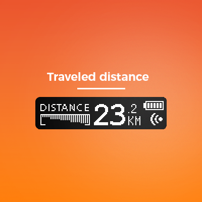
The throttle bar under the text “Distance” begins from left then accelerating, and from right then braking, while the sticks increase in height according to the value.
5 Likes
@solidgeek Looks wicked !! Simple and slick!
What about connection icon being smaller, to free up a space for voltage meter ? I think voltage meter in the corner would very useful. The connection icon can be:
Small empty circle for no connection
Small filled circle for establishedconnection
Blinking empty Circe for “connecting” ? If there is such state in the code… 
Just an idea. Keeping eye on Voltage as we all know is very important in eks8
Edit:
One more idea- small vibrator to alert on low remote battery ( 15-20%) ? This way we could perhaps free up more space on screen or use it for let’s say other alerts : low voltage on the board, faults from vers (not sure if possible) etc.
Here is one after quick google. Tiny but with more research there could be smaller ones
1 Like
The voltage will be displayed on the battery page, so I am not sure if it is necessary to show the voltage on every page? Currently, there are three pages:
- Speed
- Distance
- Battery
The remote will loop through these pages every 3 seconds or so unless you set the trigger as “Data toggle” then it will shift every time you press the trigger.
I have no idea how @Ackmaniac watt mode works, I have never used it. But it could probably be added at some point
@solidgeek I think this project would really benefit from the Adafruit M0 Proto (https://www.adafruit.com/product/2772) Its smaller than a nano and comes with integrated lipo charger/booster and usb. I have a few, ill try to modify your remote to fit the m0 and an nRF24L01+
1 Like
Give it a try! He’s throttle curve works amazingly together with watt mode. I don’t think I’ll ever go back to any other firmware. Smooth throttle control!
@Ackmaniac could you tell if your firmware would work well with this remote ?
Well if the firmware works with a standard PWM signal and doesn’t change the tachometerAbs value then it should work just fine
The Adafruit Feather are awesome, however as far as I understand they operate at 3.3V. The only thing using 3.3V in the remote is the nRF24 module, while the OLED and Hall Effect sensor requires 5V. The OLED could be supplied by a separate 5V boost converter, however, the Hall Effect sensors max output would be too high for a 3.3V logic, so a voltage divider would be necessary. It should, however, be possible to find a Hall Effect sensor working at 3.3V.
The Adafruit Feather could surely be a cool substitute of the Nano, TP4056 and boost circuit. I am looking forward to see your modifications
1 Like
@solidgeek, the hall effect sensor works fine with a 3.3v source, it’s out of spec but works fine and it’s ratiometric so it’s output is proportional to the input. Adding a tiny 5v step up would be very easy for the screen
1 Like
Well you are probably right, however, I am sure there is a reason why the min voltage is 4.5V. The output might be unstable or unable to detect the same min and max values, and I don’t think that’s an option then driving 40km/h on a skateboard. Using the Hall sensor out of specs only adds another way to face the asphalt 
I think a better solution would be to find a Hall Sensor that is working correctly (within it’s specs) at 3.3V, or simply find a way to supply it with 5V
1 Like

Let’s do this
A couple of thoughts: a sort of lip on the sides would be good to have so that the halves fit together without a wobble even when not screwed together. Also I’d prefer screws with nuts on the opposite side instead of cutting a thread in the plastic - that would make reopening a lot easier.
7 Likes
I ordered a few sensors (TI DRV5053 variants with different sensing ranges) these are 2.5-38v input and 0-2v output so well within spec. Ill try and print a case this weekend and give it a try! I ordered a oled screen as well, 3.3v operating voltage as well
OLED consumes ~20ma NRF consumes ~15ma And the proto m0 can provide 500ma regulated 3.3v, i think this might work very nicely
3 Likes
Regarding the screws can also just put a retaining nut into the plastic so you don’t need to have screws on one side and nuts on the other, just boolean/extrude/cut out a cube slightly bigger than the nut from the cylinder of plastic the screw goes into. Can also widen out the holes themselves in that case and let the screws freely drop through the holes until they get to the retaining nut did this with my remote and it worked well I only have 1 screw on mine though so it can be swiveled open pretty easily which is good for tweaking things and charging since I didn’t put a charge circuit in the last one I did think you could get away with just 2 screws for closing the case though especially with a lip added.
I have almost the same guts in my controller except minus the OLED and using a 800 mAh battery it lasts incredibly long, have left it on by accident overnight a few times and was still pretty well charged, your numbers are pretty accurate, the nrf chip plus arduino for me was consuming between 18-20mA. Actually speaking of leaving it on overnight not sure if that’s in the code already but might be good to add in some stuff about excessively long times without input to just shut off the radio at least (not sure what you could do in terms of lowering power consumption of the arduino too but it’s pretty negligible itself anyhow).
Well there is an interrupt based sleep on arduinos: https://playground.arduino.cc/Learning/ArduinoSleepCode
not sure if the nano can actually benefit from this.
@solidgeek BTW guys, would you know if there is option for implementing a long press of a button to switch on and off the remote ? Most of today’s devices have this as standard and I think it would be better than the actual switch. I think it would be more hardware based than code based. Any thoughts ?