Hence why I said leave some headroom on the low voltage cutoff
I’m merging conversations here, but headroom for however many S in voltage you are boosting with… ?
I’m going on my third beer, doesnt this defeat the purpose to begin with? I do get this makes sense with differing internal resistance though. Forgive me for combining conversations… I’m asking if you are charging your main pack and not your voltage boosting pack at the same time.
I’m not saying that much, probably 10% of the total pack capacity including the booster would be fine.
Ideally, just stick an RC low voltage chirper on the booster pack.
1 Like
Before I go forward, I want to get the community’s thoughts on my plans to see if there are any blatant issues or dangers with what I want to do. I want to do the original range extender this thread was based on (but as a voltage/speed booster) plugged into a loop key, in addition to my current range extender plugged into the charge port.
My current 24v power tool battery swapping mechanism to boost converter (42v 5a) plugged into the charge port works great for my 10S4P 25r 10Ah battery… And I intend to keep this at the same time as having the voltage boost option in the loopkey… I’m assuming this will be fine, charging 10S at 42V while boosting the output of all that with another 2S pack that’s not being charged.
Now, I want to splice a loop key into the red wire that leaves the pack and plug either a loop key or a 2S18P pack of Samsung 30A (6a discharge / charge = 108A, need so many P to not stress the cells and provide at least 80A to match the rest of my 10S4P packs max output) It would be a 45Ah pack based on my testing of each cell.
I would maintain 10S voltage cutoffs and just keep an eye on my 10S batteries voltage via the % lcd on the pack and my power tool range extender’s voltage monitor connected to the 10S pack, and rely on the BMS cutoffs as a fallback if those fail me somehow or I get blackout lazy for some reason (not expecting this…)
I would monitor the voltage/% of the 2S18P voltage boosting loopkey pack separately with another external voltage display, and being 45Ah I don’t anticipate it draining even half before I can fully recharge my main battery with all the external batteries I have. This I think will have the benefit of not needing to charge the “speed boost” pack as much and/or maintain a higher voltage slightly for the duration of my rides.
For charging, I don’t intend to use any kind of BMS, instead have two barrel connectors, or 3/4 bullet connectors and just connect these to contacts in a 3d printed 18650 sized shell that I will simply slot into an 18650 charger to charge the whole pack at 2amps. I’d expect this to take forever, but I’m not trying to buy a fast 4.2/8.4v charger /2S 80A BMS.
Since all the 30A cells are spot welded in 3p groups, I was going to connect 6x 3P groups with 14awg silicone wire, soldered to the nickel strips, and solder 10awg wire for the positive and ground to the entire pack and to connect between the two large P groups.
The idea is that I can carry this pack in a padded 3D printed case that I can clip onto the top of my board, disconnect the antispark loopkey and plug in this pack to the same port to instantly boost from 10S to 12S when someone wants to race or something. Do you all see any issues with any of this? I’m curious how well this will work, or if it will work at all.
As convoluted and crazy as all that is, I’m pretty sure it will all work.
In the spirit of the original post on this thread, I’ve decided to make a 1S voltage boosting pack to get a tad bit higher top speed and maybe a bit more range while I’m at it. I’ve documented the build here: https://www.electric-skateboard.builders/t/the-demonseed-tb-218-tb-6374s-190kv-tb-mounts-chibattery-10s4p-dual-focboxes-superflys/50610/99?u=skatardude10
Bench tested it and it works great. The extra voltage makes my board sound mean and scary. Ahh!! Glad I didn’t boost to 12S, I like my gearing and speed where it’s at.
Boosting voltage this way, instead of capacity, is very dangerous.
I hope you have some way to verify the packs are balanced and know if any P-group falls below a cutoff voltage.
The thing to note here is he did it through a loop key. Making a 10s into an 11s. Junk cells in a giant 1s1p config works I guess. If a cell dies it’s not much of a loss.
If the focbox is not configured, this may cause high voltage cutoff. Future readers beware.
The main packs BMS low voltage cutoff per P group, main pack battery percentage meter, and a secondary main pack voltage/watt meter. So the main pack I have 3 ways to monitor as voltage gets low, and it never really gets too low since it’s always charging.
For the big 1S pack, all the cells are wired in parallel and should balance each other. The packs voltage is monitored with a 1S low voltage alarm set to 3.2v cutoff.
As for my vesc low voltage cutoff, I don’t plan on running the 1S pack when the main 10S packs voltage drops below 36V since I tend to get sag, and don’t want to sag below 28V when the resting voltage reads 39V with the 1S pack, since the vescs low voltage cutoffs are set to 28-30v for 10S.
Good enough, or do you think I’m missing something?
Plugged in, the voltage is less than 12S, 46V both main and secondary battery fully charged. My high voltage cutoff is set to default at 57V I believe.
Pack works. See post on build thread: https://www.electric-skateboard.builders/t/the-demonseed-tb-218-tb-6374s-190kv-tb-mounts-chibattery-10s4p-dual-focboxes-superflys/50610/100?u=skatardude10
1 Like
To be very precise it should be called portable charger on the go.
2 Likes
Skimmed through the whole thing. Cus I’m a lazy mfker. Did OP end up doing the 2s5p external pack?
For the 10s to 12s boost, it would only work if it’s plugged into loopkey and cell voltage difference between internal and external pack is small, and Metr to reflashing the # cell and voltage cutoff settings. Otherwise, you might risk completely destroying the internal pack when you run it dry.
I’m thinking of making a 13s1p pack with my cheap 2000mah Sanyo18650UR for my Hummie. Kited with a cheap charge discharge BMS and boost converter to plug in at the charge port. Does anybody know if the BMS will limit current draw or should I just get a boost converter than has a limited Current rating. (Will essentially step up to 54.6 voltage applying CV to the charge port all the time until discharge bms cut off the external pack)
Edit: actually I’ll be setting the boost to 52v to be safe, cus I don’t usually fully charge my batteries anyways unless I wanna be a fast boi that day. Oh and that pack will only be used as a range extender.
What happens when I plug in 52v at the charge port and international pack is higher?
Well I’m finally getting around to getting this implemented on my board. Thanks to everyone who’s lead the way on this.
The key thing for me with this add on is to have a range boost that can be added in seconds when needed and then removed in seconds leaving my board all sleek and beautiful again.
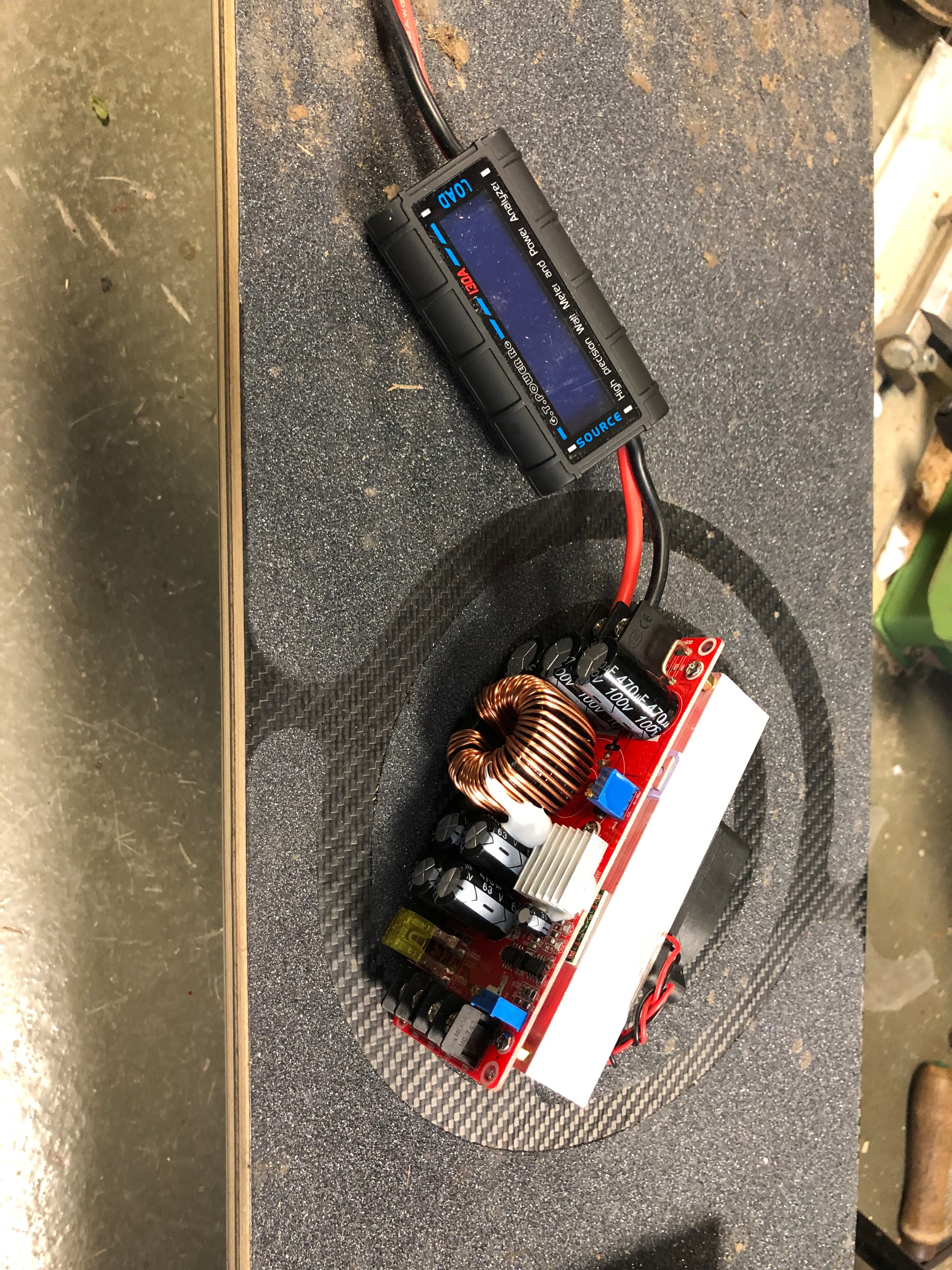
So far I’ve built a 10s3p 30q pack shaped to fit above the charge port and around the boost converter and bought the boost converter and watt meter.
Next step will be the enclosure. I’m going to cnc a Delrin top and bottom with sheet ABS between as walls. I’m going to have 2 loop keys, one for powering on the boost pack and one anti spark to enable charging power to the board. The watt meter will be incorporated into the lid.
The charge port will be connected as soon as the extender is installed…


1 Like
Looking good! I have a feeling this is going to work out well for you 
I noticed that having the boost converter charging while riding was a great buffer for the reduced efficiency riding Pneumatics, so that too!
Can’t say it enough, couldn’t get by on my 10S4P without my boost converter setup. I’m considering building a 12S8P, but even then still considering continuing to use the boost converter.
1 Like
So I finally tried to build my own range extender but encountered a problem - magic smoke.
So my setup was this:
6s3p 30Q -> Protection Module -> Step-Up Converter -> Charging port
When there was no load, it was doing what it was supposed to do. But during a load, the insulation on the wires from the 6s3p going to the protection module melted and caused a short. It is possible I might have used a thin wire (although it’s the same wire I’ve been using to charge my board at 4A). Is there a minimum AWG wire I should be using on this setup? Or is there another reason why it happened?
Keep in mind that the current on your boost battery side will be greater than that of the charge current.
So if your boost converter was converting from 12V -> 24V with a 4A output, your real current draw from the boost battery would be 8A.
It sounds like your main battery was nearly full and your boost battery was low, leading to a very high current draw.
Also, the relay for switching the protected battery on and off is rated for 14V, 20A. Exceeding that could cause additional issues (this is the manufacturers fault, since the board is designed for up to 36V)
1 Like
It was actually the opposite, my main battery was 40% and the boost battery was full. After the incident, all the components still work fine. Is it worth trying again but this time using a bigger gauge wire from the boost battery to the protection module?
1 Like
Well that’s probably your problem. Was it possible that the main battery voltage was actually higher than the range extender?
1 Like
Output voltage from the step-up converter was a constant 42v.