Fogstar wholesale
Any thoughts on making a 2s6p module? Would be great for a 10s6p build.
1 Like
I’d be surprised if Agnius sold subpar stuff on his site. He’s picky as hell. 
2 Likes
I think I read somwhere that @agniusm had said that he won’t make anything more than 2S4P modules. I forget the reason. Maybe he can explain.
But based on the tabs that he has, up to 2S8P modules can be made.
He isn’t going betond 2s4p as it’s way too long and it would be subject to even stress on the case
So I tried 3 connection techniques. Left to right
- vertical crimped 10AWG wire.
- Horizontal crimped 10AWG wire
- bus bar(similar to agniusm’s bus-bar)
So this is my impression of the connection technique.
- The vertical crimps would work well with flex but adds some height to the battery.
- Horizontal would work well with flex but adds a lot of gap between modules
- Bus-bar would be problematic because it would make the joints rigid. If the bus-bar were a bit longer it would allow the modules to bend relative to each other, but at the cost of rotational friction where it comes in contact with the screw.
To make joints flexible, I am thinking of making some copper sheet metal part so that there is some flexibility. Will post a solidworks model soon.


5 Likes
Interesting. I thought @agniusm’s busbars would allow for some play for a deck with some flex as the bar rotate back and forth slightly as the packs would move.
Haven’t seen a complete setup with the busbars yet though
Honestly, just from looking at the picture, the inverted connection would only be great for flexy decks. The second connection is great no flex to medium flex and the third would be great for no flex decks. I dont see why all three arent viable options. Just my .02
Edit: agree on second connection lol.
1 Like
I edited my post above to structure it better for discussion.
I think 1st and 3rd are both good, but one is for flexy and other one is for rigid decks. 2nd just introduces too much of a gap.
3 Likes
Would the third be ideal for a Hummie deck? Thats what i plan to use these on. I’ve reaf that there’s a slight flex to it so I figured enough for the busbar option sold at @agniusm’s site
Is say go for the first connection. Its more suited for flexing.
1 Like
Guys, you are overthinking flex. Cut out a piece of wood that is the size of 2 modules, and try to flex it. It wont flex at all and the bus bars i have have oval holes to allow for some movement. The flex ocurs over the length of the board and if you divide that up the joints between modules have minimal flex which are covered by the series bus bars. Sure if you compare 1st module and the last the deformation is significant but nothing to worried about modules next to each other. Just my line of thinking.
1 Like
If you are obsesed, one more option would be to use copper braid. Flatten copper pipe of similar size, insert a braid, hit it with a hammer and drill 5.5mm. Do that on both ends and you have flexible link
2 Likes
I agree but think of a Never Summer Heist deck. Made to flex lol. Now I would never diy my Heist lol. Its just too pretty. But if I did, I would definitely go the first connection. It would allow the room to flex with the board. I’m not trying to argue anything lol. Just see functional applications in all three.
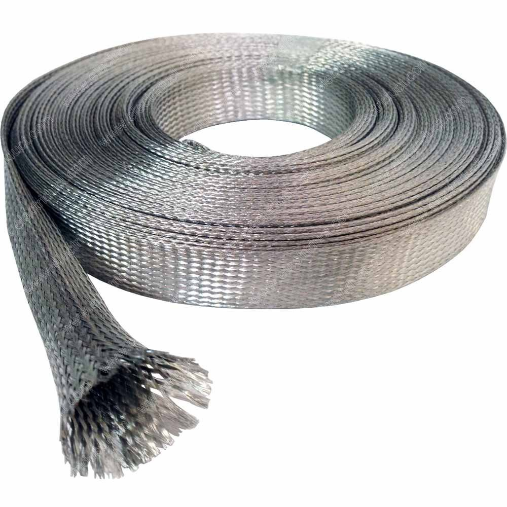
I actually really like the idea. Just got this. Might make it simpler by soldering the ends to keep it from unravelling and poking a 5mm hole to let the screw in.
3/8"(9.5mm) wide(when flat) and 1mm thick(when flat) should be plenty as a replacement to the bus bar(I do realize that it’s better for DC current to have a solid block than lots of surface area). I got 10ft of it. https://www.amazon.com/Tinned-Copper-Metal-Braided-Sleeving/dp/B01MEG9V2R
1 Like
Which size are you going for and length? Looks promising and able to survive heavy flexing 
I edited my post above to answer your question 
1 Like
This is what you might be making:

13 Likes
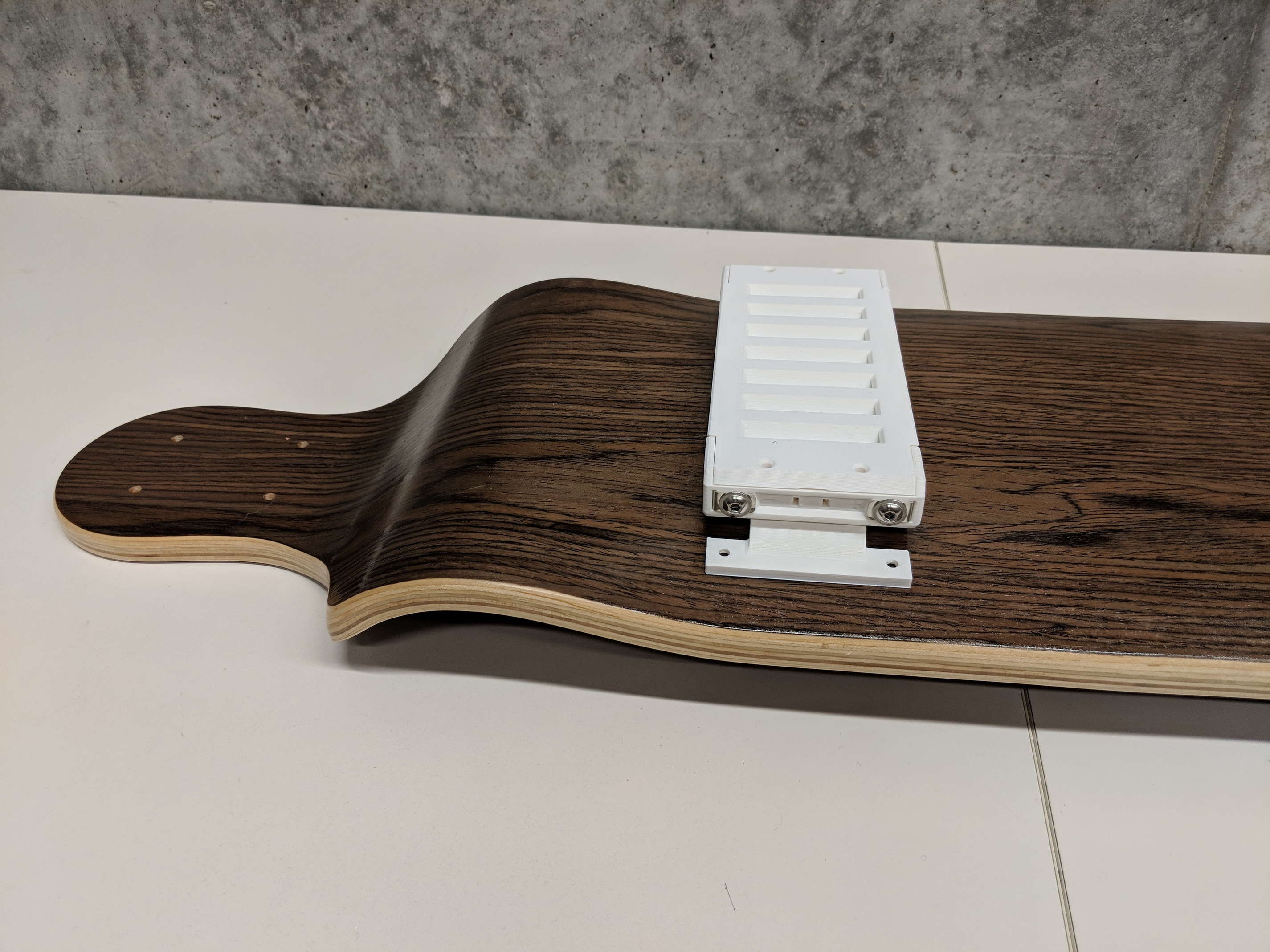
Ok so while waiting for braided sleeve, I decided to figure out how to mount individual modules on the board and this is the prelimnary idea that I came up with. basically this plastic structure is how you easily connect to the deck while providing a bit of play in up-down and left-right direction to absorb shocks and account for any small flex. I think it would be a lot better if I use some elastic material to print this out. Apart from this mount. I’ll have an enclosure for dust and splash protection.
Do you guys have any suggestions to improve this or any different mounting idea? I think the first change that I have to make is to reduce the gap from the deck.


8 Likes
This Looks Epic
1 Like