Correction its not the u401 component but the MCU or U1 component… considerably more difficult to replace lol but might still give it a try and see if I can fix it
1 Like
Visually there is no sign of  . Are you 100% sure its the esc? Did you try to bypass the BMS and see if it works. Or trying a different esc with the BMS connected?
If you don’t have any extra esc’s to test, maybe one of the other forum members could help you out if they live close. Share what city you live in to see if anyone is close by.
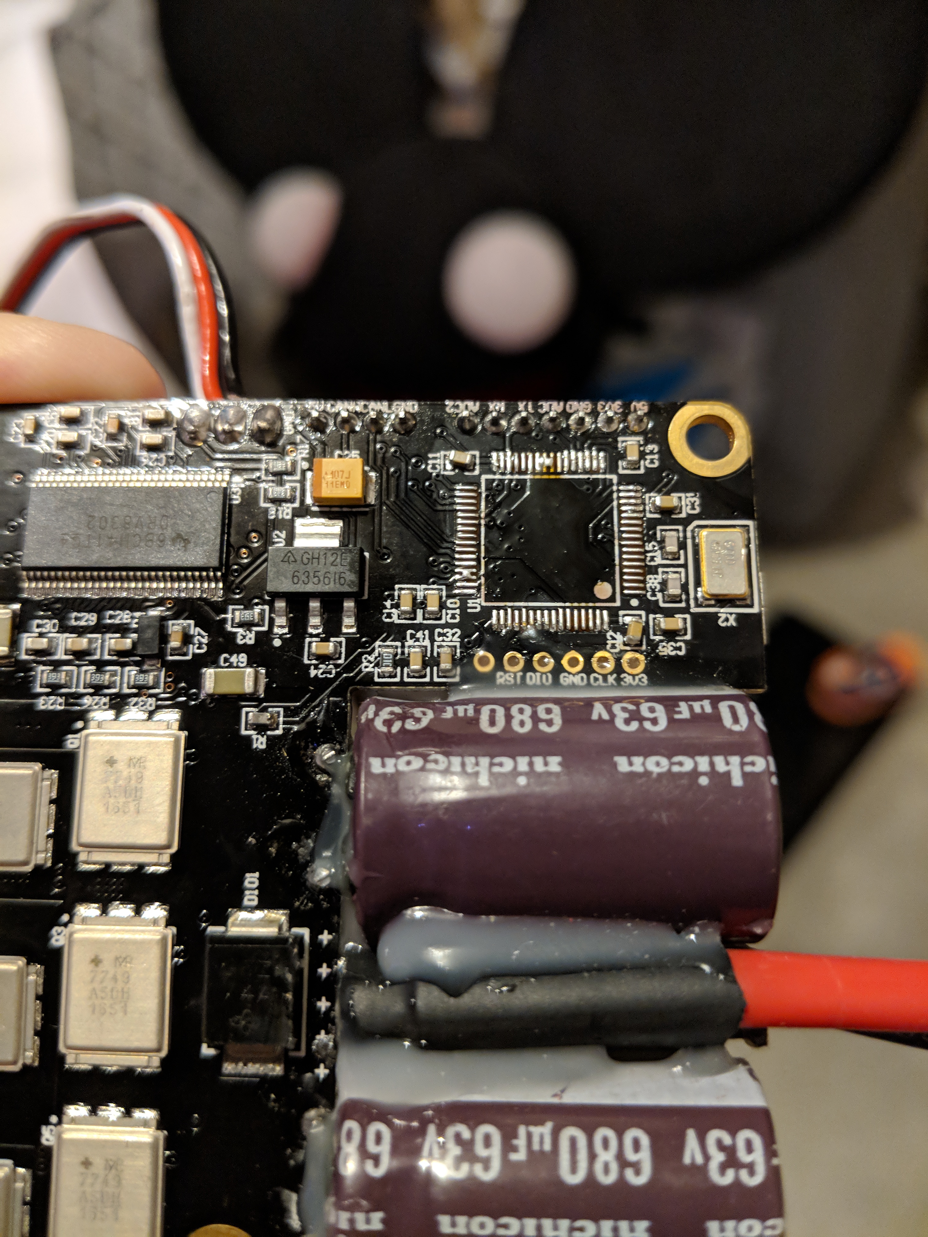
I did check to see if I’m getting the correct voltage after the BMS and that looked like it was good. Based on the fact that the positive lead of the battery shorted out on one of these two screws

@JohnnyMeduse (who was recommended to me by a few others on the forum as one of the most knowledgeable people when it comes to troubleshooting a VESC) said it was most likely the MCU on the VESC. I spent a lot of time today researching how to replace that chip as its pretty small and had a ton of pins on it. I’ve got a replacement coming tomorrow and the bad one is already been desoldered.
1 Like
Well good luck on the repair. I tried to replace a DRV once but just ended up desoldering a bunch of other components. lol.
This area in blue also looks like a good way to cut the wire insulation.

Maybe a 3D printed cover for the BMS would be a good idea. I do like your printed mounting brackets, very neat.
1 Like
Get two focboxes so you don’t have to wait weeks when they go bad, when the build is reliable sell the focboxes you still have in stock.
Please post your VESC current limits here, you might have killed the controller with wrong settings and might kill a second one if you keep the same settings
4 Likes
I agree ![]() if I’ve got time today I was going to try to design and print some cable management stuff. I’ll be sure to share the end result
if I’ve got time today I was going to try to design and print some cable management stuff. I’ll be sure to share the end result ![]() If anyone is interested in the other parts I printed just let me know.
If anyone is interested in the other parts I printed just let me know.
edit: Also regarding your attempt to desolder the chip, I ended up using the kapton tape to mask off the rest of the board and then took my high temp heat gun and a slowly warmed up the chip and solder. I used a temp gun to try to gauge when it was warm enough and not too hot. If you look closely you can see that 2 of the micro caps shifted a little but they are still making good contact so I should be good. now I’m just worried about the soldering part. hopefully with enough flux that will go well haha. Also I really melted the plastic plug on the back side of the vesc… luckily I have some extras getting delivered today. I’m under the impression I have to flash the new MCU chip so I plan to follow this thread: VESC Boot Loader Installation Tutorial to do that. If that is not the correct thing to do please let me know.
I don’t think it was the current limits. I was working with @mmaner to get those right. I had the max motor and batter current set to 60A. Before I do anything though I’ll be sure to share what I have in the tool so I don’t accidently overlook something.
1 Like
Quick question. Any of you have an extra 7 pin socket? I melted the one on my vesc by accident when removing the bad MCU. I’ve got some extra 6 pin sockets but not the 7 pin 
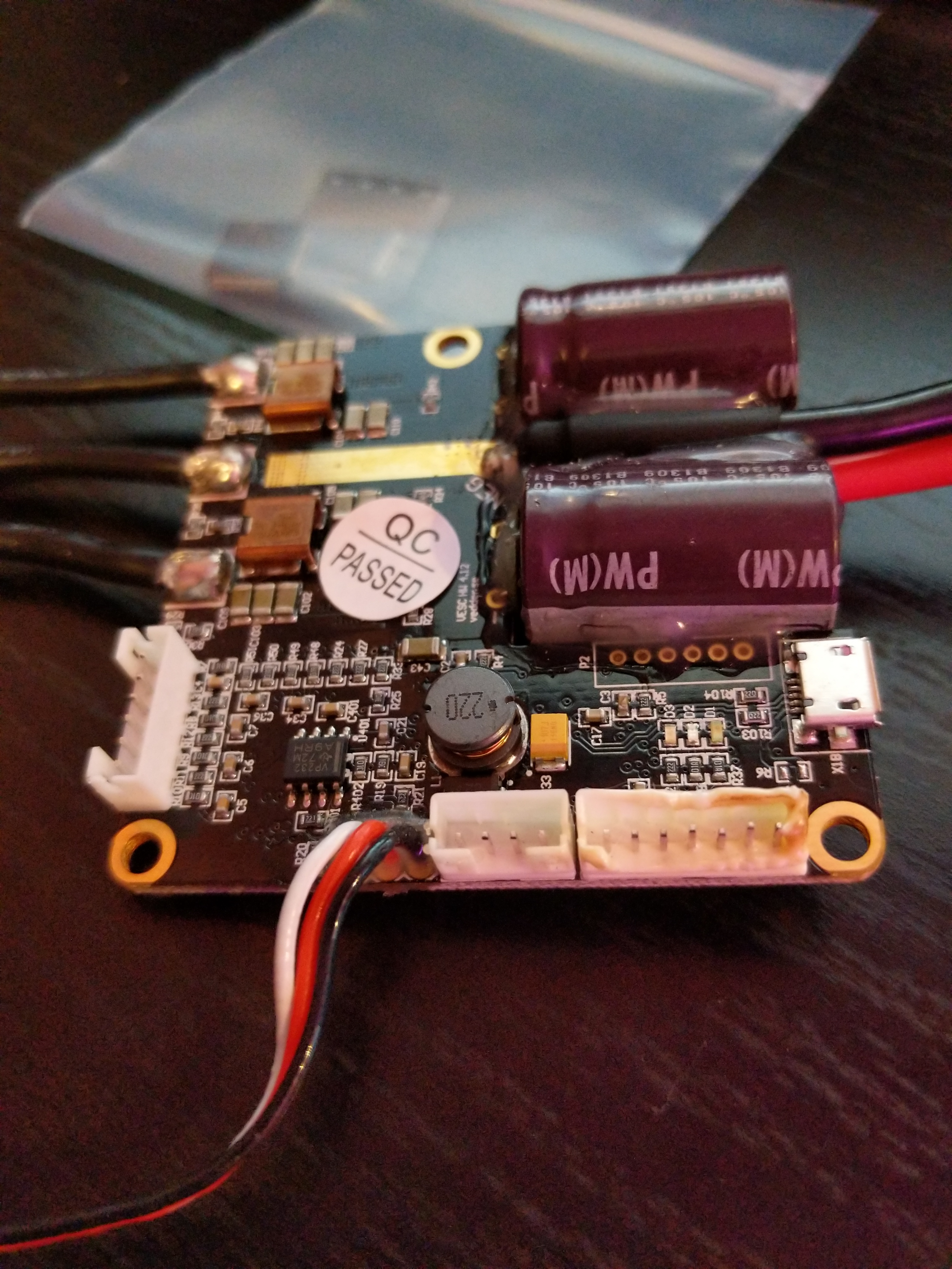
Hey guys, So I got a new MCU soldered onto the board, just now finally managed to get the correct firmware flashed to it and I think I’m ready to start inputting setting for the build. Last time I was running the board sensorless in BLDC mode. But I was hoping someone would be willing to help guide me through a hybrid setup where its FOC mode in low eRPM and BLDC in high eRPM. To help get the ball rolling here is my build.
BKB 6374 190KV 3200w motor Bestech BMS Enertion FOCBOX 10S3P Samsung 30Q Li-Ion battery
Any advice is greatly appreciated. I’m not sure exactly how to enable the “hybrid” mode I’ve heard about.
not to shoot you out of the sky, but you should probably just set it up in BLDC first and see if the focbox responds well to it 
thats a good idea  I’ll do that now and let you know how it goes (not sure if it will stop raining today but if it does I’m dying to get out and ride again!)
before you disconnect the focbox why not take some screenshots of the values that you have? Maybe thats what caused the initial issue? 4.xx hardware is pretty finicky… or so ive heard 

I can do that, I was running 60A for the motor and battery max, -30A max break and -40A max recharge anyone think that would be a problem?
well 60a is kinda high for even a focbox with no cooling solutions… So be careful of that on your ride.
Whatever you do dont full throttle unloaded motors, thats a pretty common vesc killer
I mean if you need 60a, then you need 60a and I cant tell you to go lower… but maybe 50 is a nice compromise? Battery and Vesc wise
1 Like
wait 40a max recharge? this sounds funny to me ( at least for a 3p battery?)
… I havnt opened bldc tool in months

like this?
well I’ll try those settings. However when I get the the motor detect step I hit “Start Detection” but liturally nothing happens, no entries in the log, no messages about success or failure… is there something else wrong with the FOCBOX?
weird…
char
P.S. the battery voltage is 40.9V so no early cutoff interference.
Another odd thing is when trying to set up the remote, it doesn’t look like the vesc is getting any feedback from the remote/receiver. The real time data doesn’t change at all. Something else I’m noticing is the VESC will disconnect from the computer after a few minutes. Is there something else on the board that I should look at to try to see if there is another damaged component to replace?
maybe add some pics of the mcu now that its back on?
I mean if its reasonably priced, might as well replace the drv yourself if you can too. Some DRVs fail without external damage
*not that this would impact your remote function at all