They don’t even really need the thermal paste.
I guess it depends on how much room is in between the FET and the case. The controller I have at least uses and needs thermal paste, otherwise the heat transfer would be far from optimal.
I use thermal tape for insulation and heat transfer and works great.
Updated STL files for housing…
2 Likes
Well I would be up for 4 of them ![]()
Considering the trademark issues that have been publicised with the latest version of this ESC (which I won’t go into), what name will you be giving your product?
StewiiESC 6.4?
1 Like
Do you have the source for that pcb?
2 Likes
Nope.
But the way I look at it. Stewii provided -the bom -stencil files -STP for the case
The cost of a single PCB through him are maybe $2 more then it would be having the files and ordering through a company like OSHPark.
The guy took the time to design them, is selling them, has extremely quick shipping. I’ll let him have the miniscule upcharge for his time invested. The schematics are open source so anyone could design a board if they so desire…
6 Likes
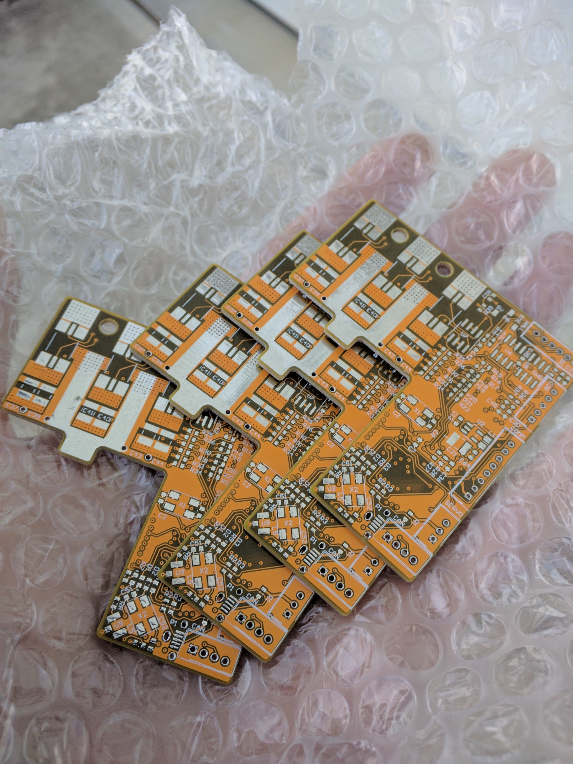
I am still not sure, I have put ESCape on the cover PCBs, I thought it was cool.
5 Likes
By the way, I have managed to connect an LED strip WS2812B to the ESC, I had to change a couple of files on the firmware tho, because BV forgot to change a few things from the version 4 so it would work on version 6. If anyone is interested I can make a small tutorial. Video
5 Likes


Did you figure out what was the problem with the sensors?
Not yet … but i think it’s the order of the pins. One thing i noticed on @stewii vesc6 ppm wires the servo and ground are opposite of Trampa vesc6. I mean they are correctly labeled on his white cover but opposite of Trampa’s.
What Trampa manufactured and the openly released schematics by BV seem to have a few minor differences like this.
1 Like
I should have all the components in by the end of the week to have 2 running 
2 Likes
Yep… lol solved the mystery… he soldered on the connector in reverse for the sensor wires.
Again he does have it correctly labeled on the white cover… so no error there but you will have to reverse the wires in your adapter or flip his plug around.
Look closely…

3 Likes
Would you be able to connect a high kv motor and make a test to see if the ERPMs could at least reach 100,000 on the bench?
Sorry, I think i might asking for too much 
No it’s fair to ask but unfortunately I don’t have any high KV motors. I had some 6355 230kV motors but sold them on forum as i kinda am not a speed demon but prefer the torque. Even with those i was highly limiting the amps to about 60A and got only to about 52,000 rpm.
All my motors are max now at 170kV 
High KV motors are growing less popular around here. I mean i get the use case we definitely need them to test the 100k limit of the DRV.
But i don’t have. Maybe @scepterr, @Pimousse, @Vanarian, @Surfer ? There are lot of owners out there now.
I only have 160,170,190 test with And these escs will ultimately be going on my carvon v4xl build I think those are around 100 But one interesting thing I think to try will be running both motors off one ESC…
1 Like
How would you connect them? Y connection on phase wires and then to both motors?
How would you perform motor detection?