Doesn’t that cost extra, though?
No, i believe it’s all included. Better to ask him directly though.
But why have to pay more for a hanger when the board has one already? I’m confused
I can’t quote you on the price. But it’s comparable to other offerings. But the hanger is a part of the kit (I believe). So you’re not paying more. Also, the precision hanger ensures an exact fit, which is something you can’t get on a cast hanger.
So for anyone unfamiliar with direct drives and Trampa hangers, a few pieces of information:
- Trampa’s components aren’t always “to spec”. Parts coming from Trampa can be a few microns thicker or thinner, hence things like the notorious wheel wobble caused by hubs not seating the bearings flush. This is the root cause of the whole hangar fiasco.
- There are three vendors of direct drives (so far). Kaly (Kaly drive?), Kug3lis (FatBoy drive) and NoWind(Etoxx drive).
- To deal with the manufacturing variations, each vendor has their own solution: Kaly drives come with his own CNC’d hangar (not from trampa) by default, etoxx drives have the option to send in your existing trampa hangar for machining or buy one from them to go with your drive, FatBoy drives come “as is” and it’s up to you to fit them on your hangar (any of you correct me if I’m wrong, this is me speaking from my own and other’s experience)
tl;dr trampa hangers are a pain so drive vendors/users have to deal with them
4 Likes
The ATB 5:1 drives are self fit no machining and not sure if 3DServisas will offer them again @Kug3lis
They also offer a mini 3:1 drive where you send in a hanger, tbh probably the best route
The magnets for the remote came in so I did a few tests using a spare arduino nano I had lying around
3 Likes
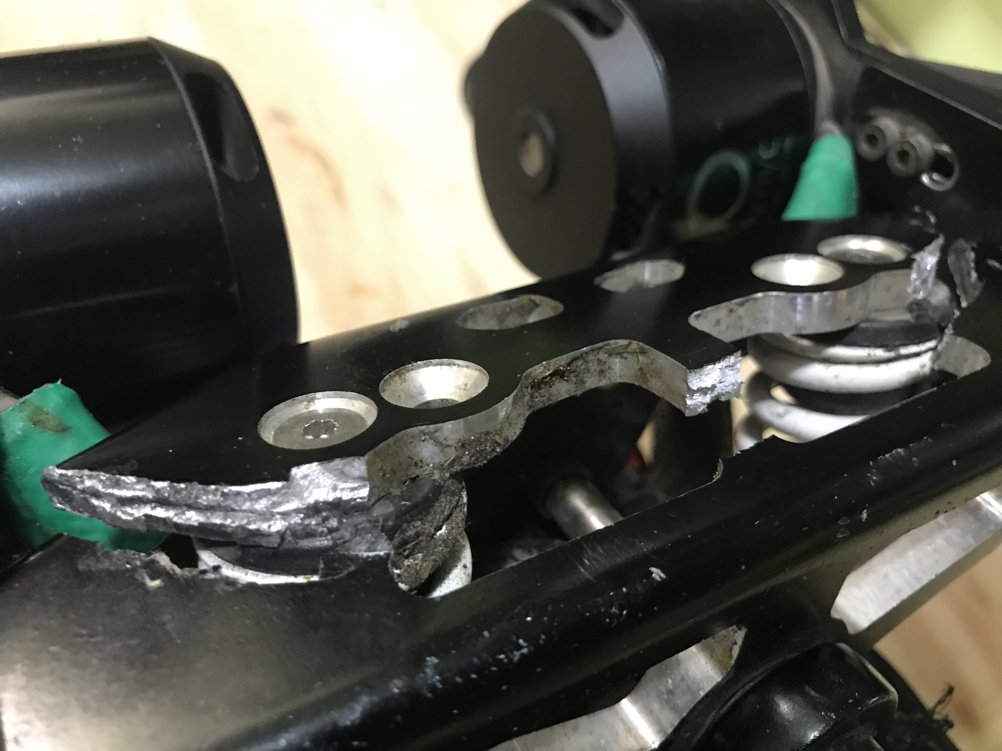
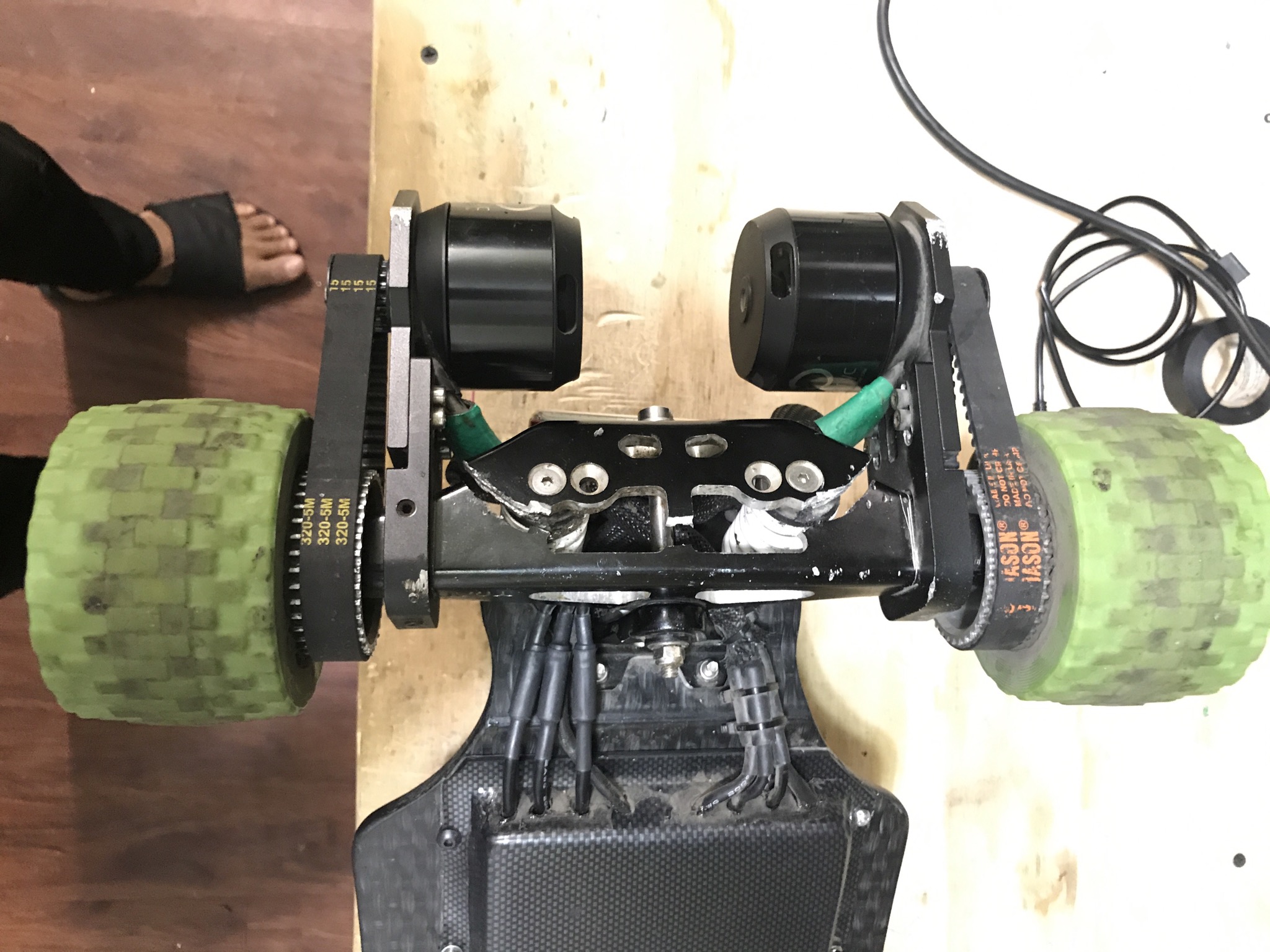
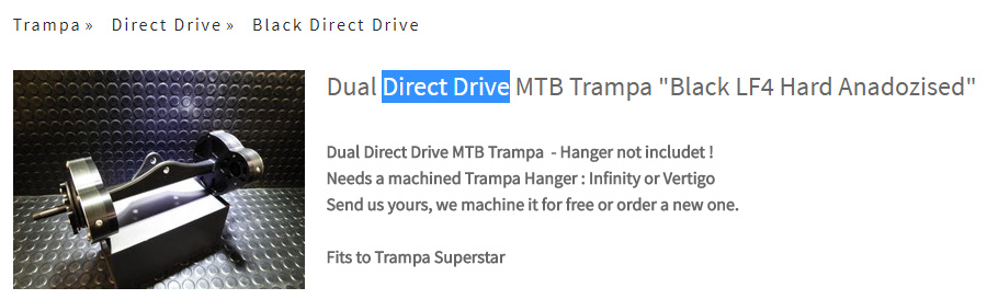
This is the reason for a 100% CNC made hanger.
The original hanger is made of cast aluminum and has a lot of imperfections, that makes it hard to properly align a belt drive and much less Gear Drive.
Also the fabrication is inconsistent causing all original hangers to be different which makes it really hard to install a precision device on the it.
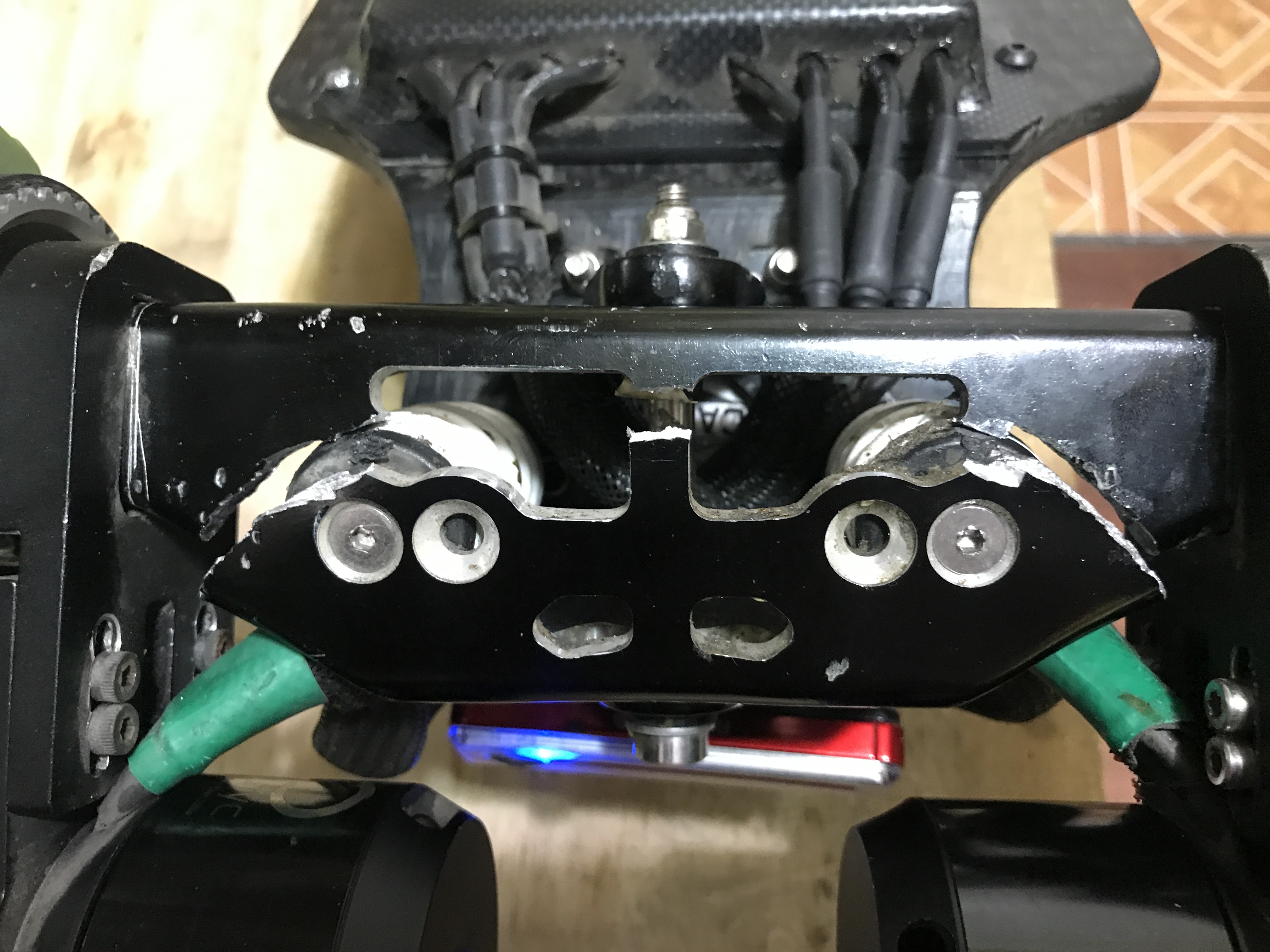
But more important is that the cast aluminum tent to brake under normal conditions if use in the back position, where is subject to big stress and that is just unacceptable.
Maybe this will clear it up.
9 Likes
Update: Just finished a working remote! Hooked it up to a receiver with a servo attached to it (which works out since ppm control on an esc is essentially servo control) and it works! I’m probably going to make a new one though since I did a lot of mistakes on this first attempt, most notably messing up the threading on the screw nearest the palm and forgetting to replace the resistor on the charge board so it doesn’t charge the battery at 1 amp (too much current for the lipo). Plus now that I have a better idea of where components are and how they’re connected I can do a better job at cable management.
1 Like
Wow from braking only?
It’s not from braking but from the nature of cast aluminum, it is just not as strong as other methods
Vibrations, material fatigue, and one fateful strike.
1 Like
ahh, the good old trampa hammer’er’in
3 Likes
Not just for bearings! 
1 Like
I had to use hammer to hammer in metal part of spring retainer as it was spinning loose inside the plastic  So I guess that’s counts as hammered part too
Patent pending
1 Like
Hi everyone,
Got my batteries in and I’m starting to figure out how to put the electronics together. This is where I need some help from the community.
I’m using @Eboosted’s double stack enclosure and I’ll be fitting my 12s8p along with the BMS inside it. Focboxes are externally mounted.
General layout is as follows:

Series connections will be done using two 12awg wires. Balance connectors (not drawn) will be in the middle.
A column of batteries from that layout would look like this:
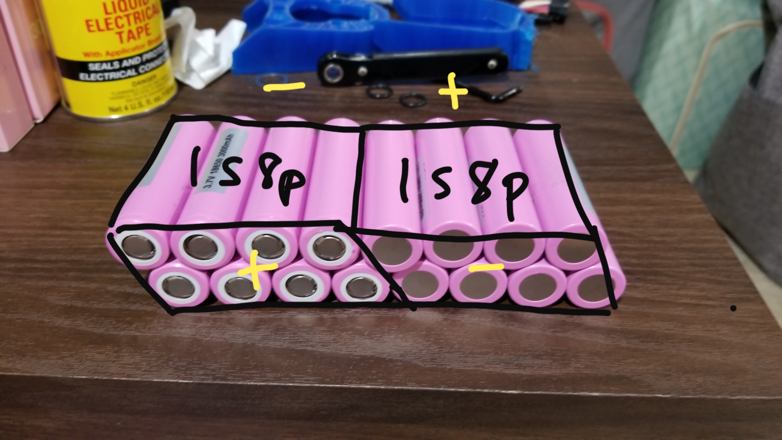
If this were the column of batteries nearest the BMS, the left 8p group would be the 1st cell in the series and the right 8p group would be the 12th cell.
I plan on using a bus bar (probably a charging PCB) + nickel strips for each 4p side of a cell and add a layer of silicone between the two 4p layers like so:
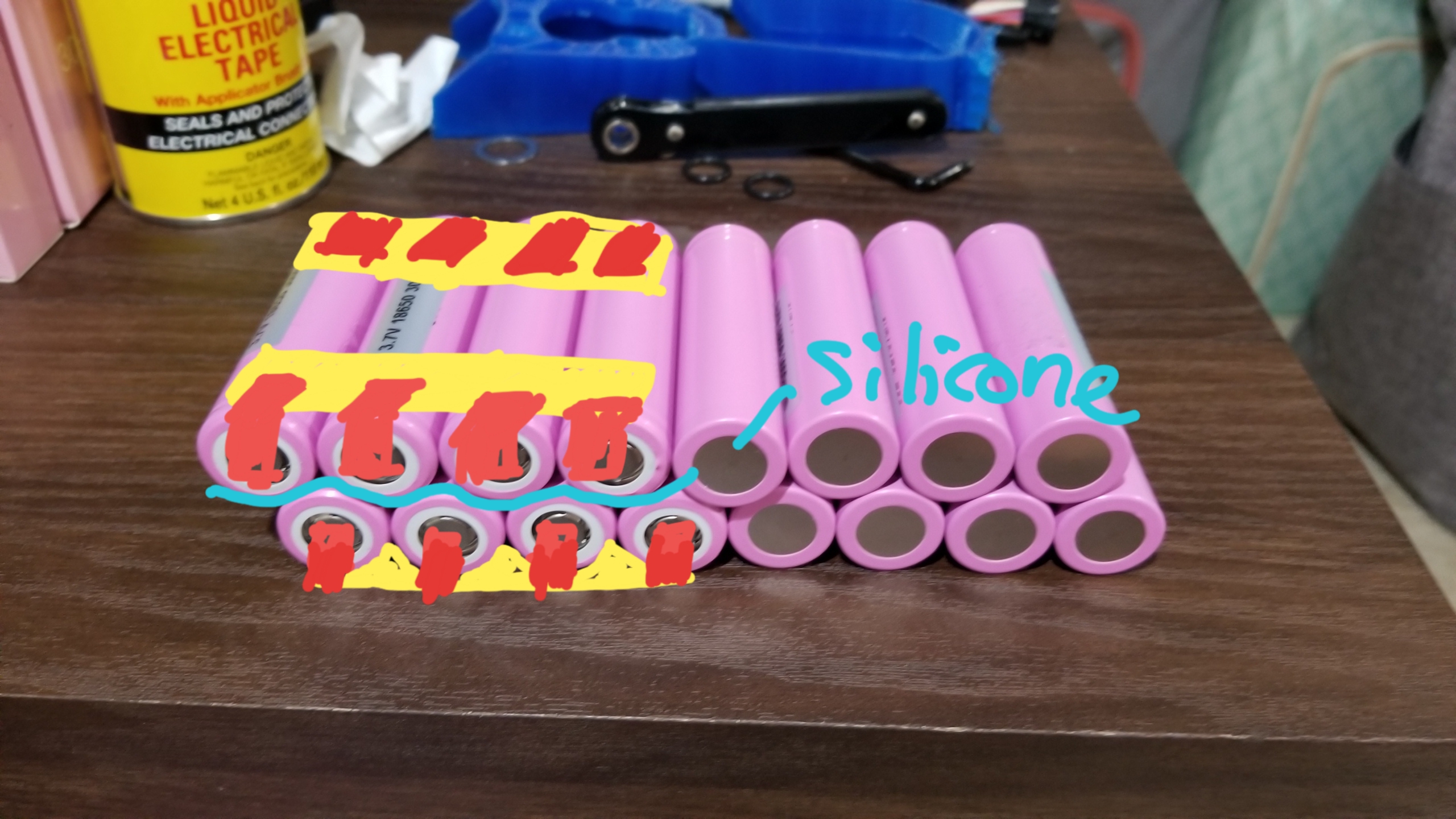
Now here’s where I need feedback. I have to ideas on how to connect the two 4p packs into an 8p pack:
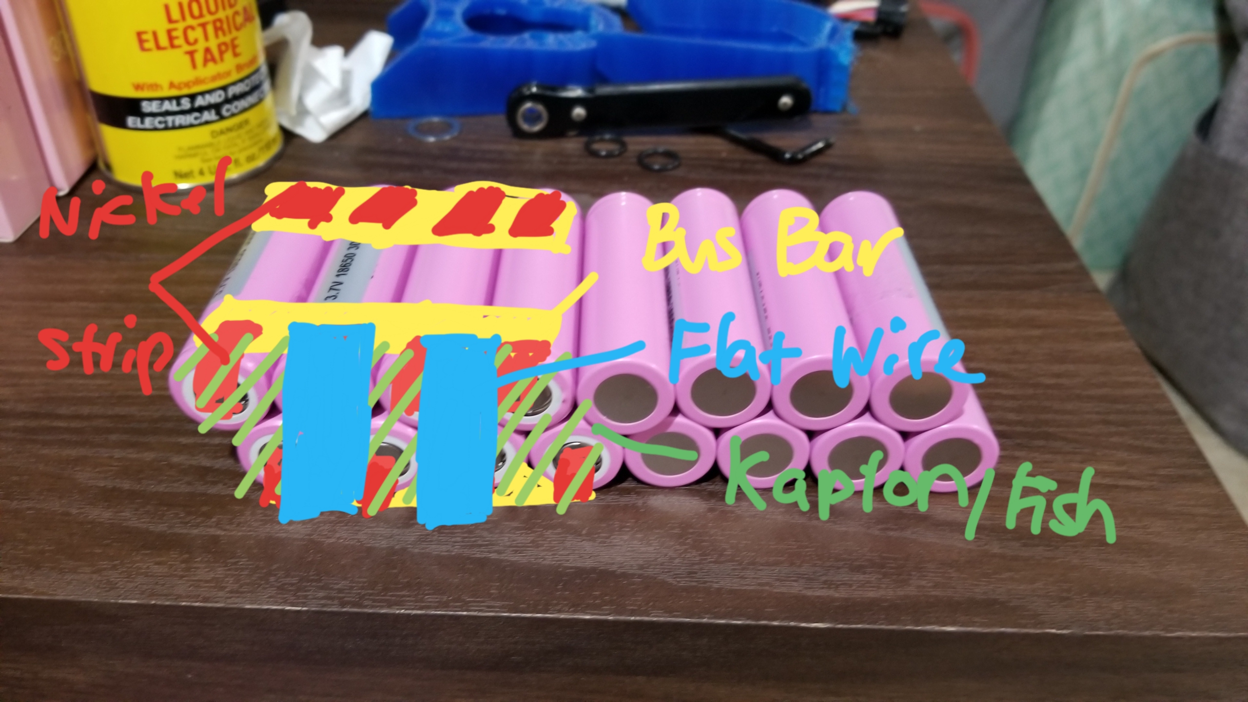
The first idea is to wrap the exposed strips and terminals with an insulating layer (kapton, fish, or both) then connect the top and bottom bus bars with two flat wires. This preserves the flexibility of the nickel strip + bus bar combination in that when a single cell in a pack goes bad, I can just remove that cell and its nickel strip from the bus bar and replace it with a new one. No need to ruin the existing welds on the other cells.
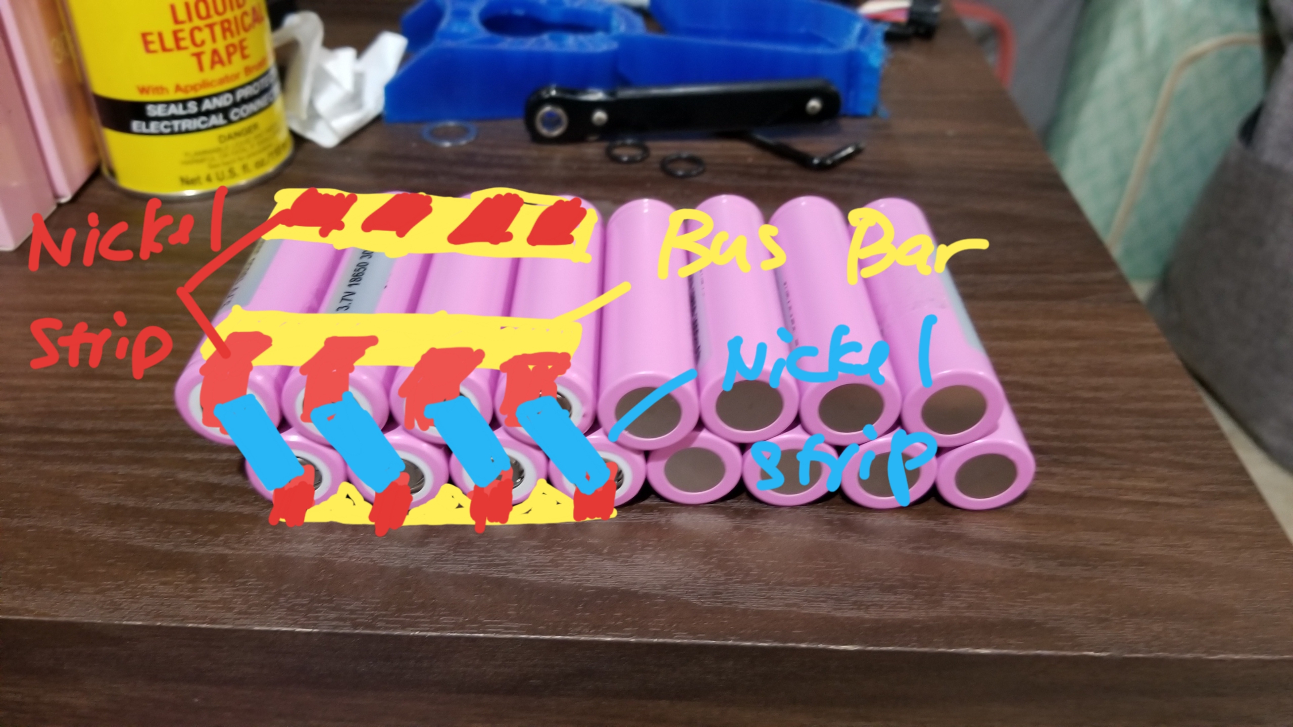
The second idea is keeping it simple and just welding each cell from one layer to the corresponding one at the bottom. I feel like this has less points of failure, but when once cell ends up being bad I’ll have to replace both that and the one it’s attached to from the other layer.
So yeah. Any help is welcome. Also tell me if I’m doing anything wrong.
2 Likes
You never mentioned the thickness of your nickel strips. What do you plan on using?
Edit: I like doubling up on .15 nickel strips for parallel connections. Then a single .2mm on each cell to connect to the pcb
None of these are Direct Drives. These are All Gear Drives
2 Likes
Alright Mr keyboard warrior, I’ll bite.

Etoxx calls it direct drive, Fatboy calls it gear drive. If I want to be politically correct, carvon and raptor drives are what’s called “direct drive”. But I’ve already grown accustomed to calling non belt and non chain drives as direct drive.