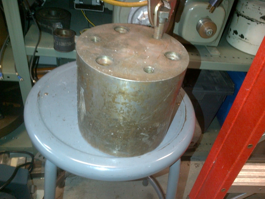
1- my flywheel is not big enough to consistently measure the torque of a system, currently a system is able to hit max speed within 100ms. My data acquisition is at a 20ms rate. I will be adding a bigger steel fly wheel machined out of steel
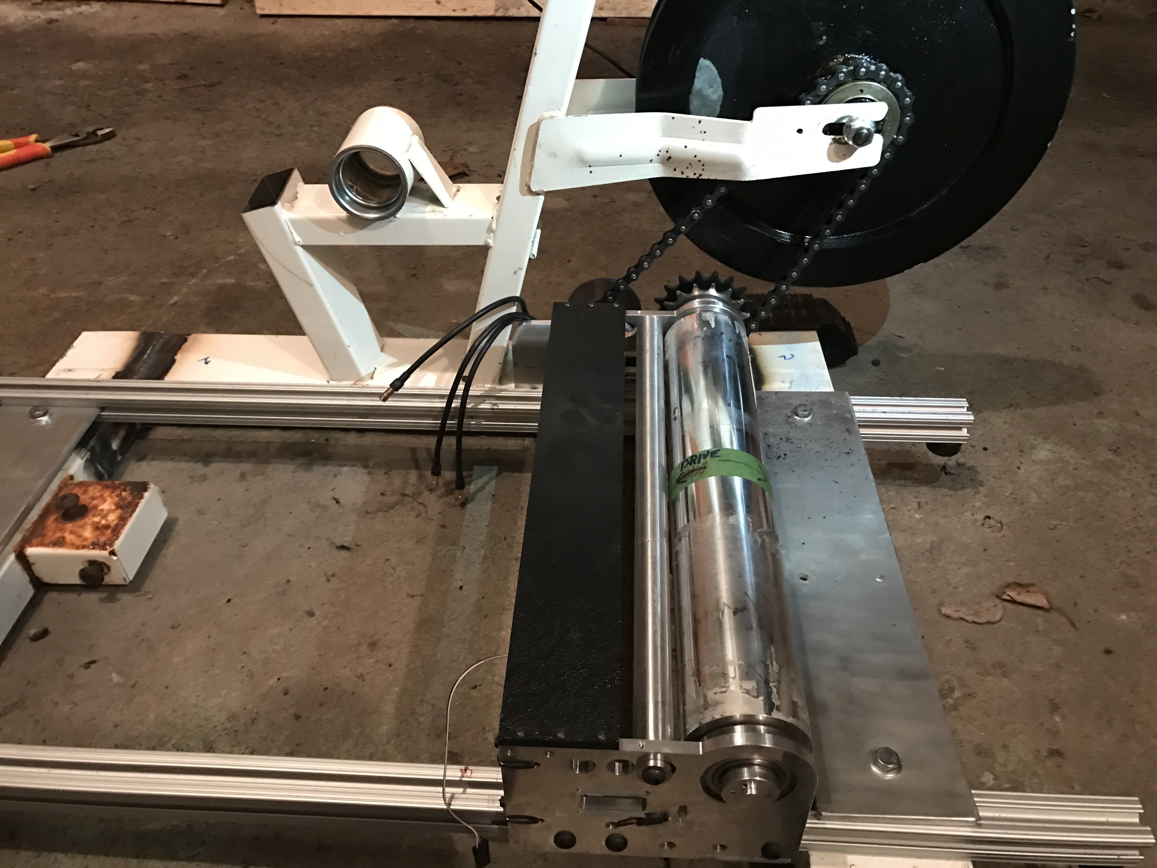
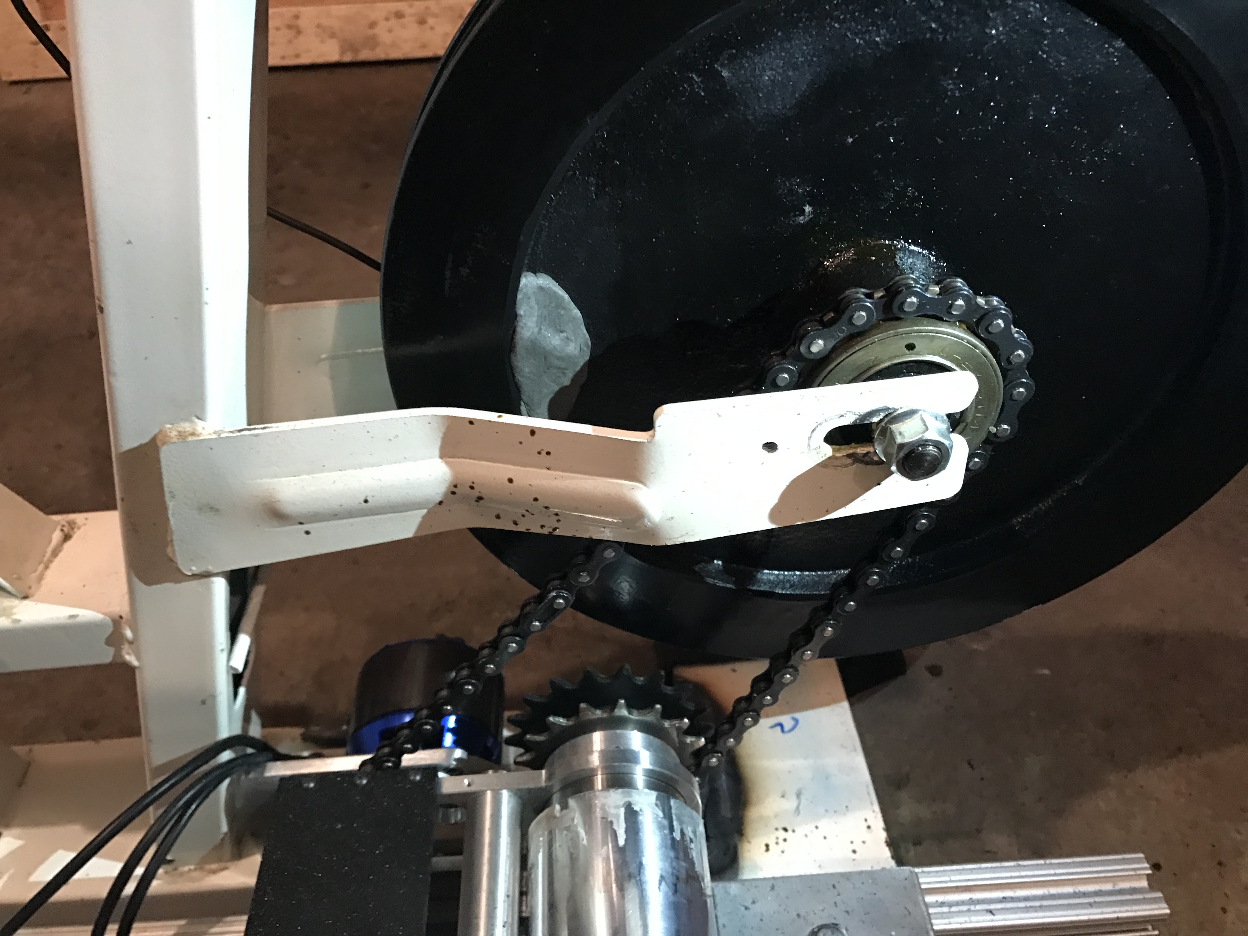
2- I’m not able to load up my system enough to get a max current output of a motor. I will be adding 2 36T pulley on each side of the drum to put 2 6374 slave motors with a pair of vesc to control the slave current ressistance
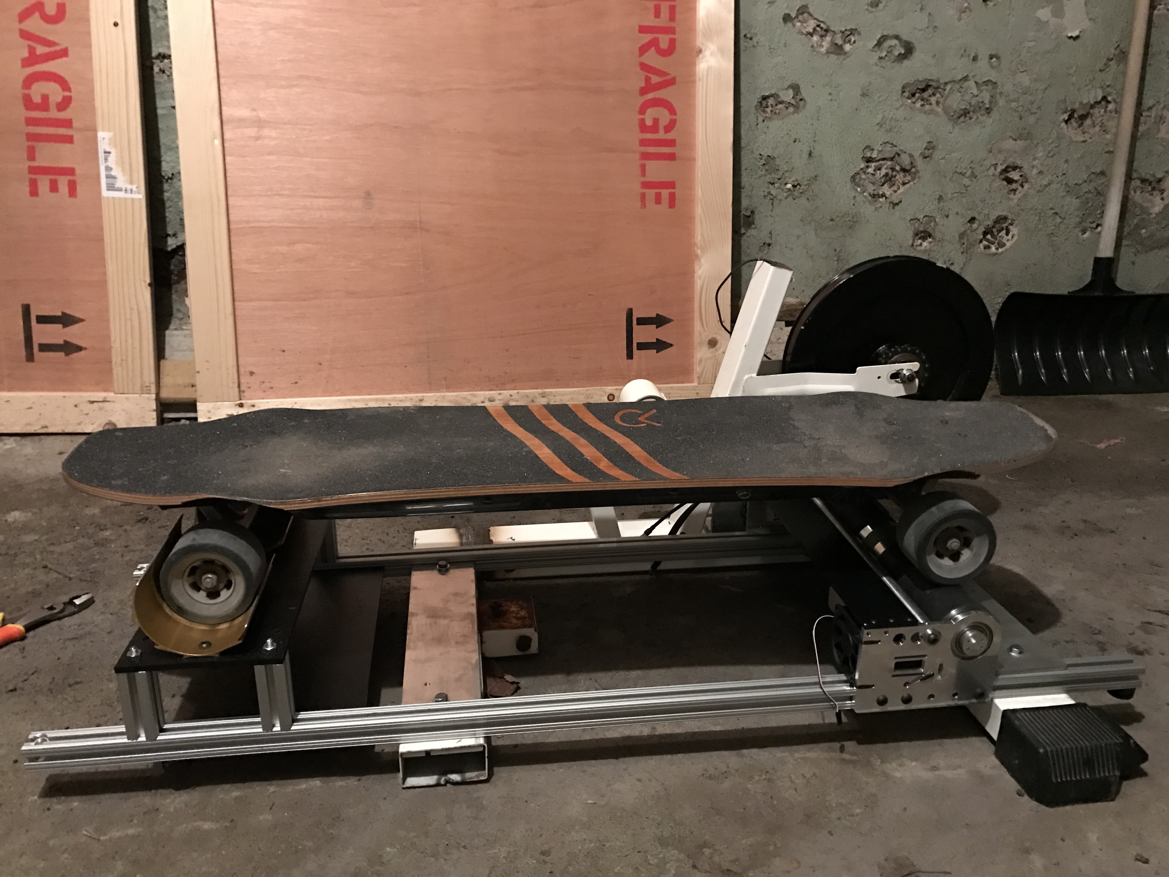
3- Get a better material to adhere to the drum, the current one got folded by the R2 ghost hubs
on the input of the dyno I have a EloggerV4 from eagle tree, this module is used to measure the input voltage, output current and RPM of the drum
I am also using @Ackmaniac APP for data acquisition for redundancy.
The drum is a 62mm diameter 13" long aluminium cylinder.
initial result with the R2 ghost 90mm hubz, I shorted one of the hubz as a slave and used only one driving hub… but I need a bigger load, still has plenty of power to go by
Cool update… post some power output data once u get something…
IT does look like you gonna need some sort of clamp to hold the boards down… the ‘‘wheel well’’ (u shape thing) looks like wont hold the boards in place
My main issue at the moment is to find the time to use it…
To get the torque output of a given system, I use @Ackmaniac’s app for the data acquisition on the master VESC.
The data will contain the following information:
-Pack voltage
-Pack current
-ERPM
-time stamp
What I still need to calculate is the moment of inertia of the flywheel, to which i did not have time to do yet…
with all that info, I should be able to get a nice torque curve.
the second system, I connect the dyno slave motor to the system, using another vesc for the data acquisition (or eagle tree) and apply a constant load on the system. I still haven’t figured it out yet, but hopefully i’ll be able to get the efficiency of a given system.
Ok, at least now I kind of get that there are 2 methods for testing this.
Im more interested in this ‘slave’ motor thing.
I can only imagine that the Rspec motor you have there is the one who is the ‘slave’ and it is also connected to vesc, where you see all the data…
Then, you just make the motors ‘compete’ against each other and measure the values in between…
Though there are still a lot of unclear parts about this… and im also not sure can you get reliable results in the method I described (one motor against the second one)
The best way to do the second way and get efficiency is to use an strain gauge or a torque wrench so you can measure the mechanical torque at once
This way you can set the ERPM on the slave VESC and them set a current on the master,this should provide a nice diagram of torque and efficiency like those that @Mellow do
would be cool if you/someone with a rig like this could attend the las vegas esk8 con… even if i can’t make it… would love to see what is what measured by a quantitative tool…
Really interested in it now. After SPD2, I realized how weak most hub motors really are. Would love to show the numbers hummies motors put out vs the raptro 2 hub motors vs carvon v3/v4 vs other cheap hub motors.
Was discussing this very topic a week ago with @psychotiller… With the speeds and power were making it’s getting to a point where road testing the limits of a high performance vessle is becoming more hazardous than necessary… Along with the WR board taking shape so is a prototype for a stand on Fluid Dyno. The layout will be a simple hydraulic pump plumbed to a resivour with a ball valve for pressure regulation. The pump will be driven by a small barrel, floated and then attached to a one Foot moment arm that will push on a scale… the setup will strap the board down and the operator will weight the board, regulate the fluid back pressure, read torque output on the scale and be able to sustain loads over time to exploit performance weakpoints without sacrificing skin and blood… I think this may also be a good test tool for diagnossing speed wobbles under load.