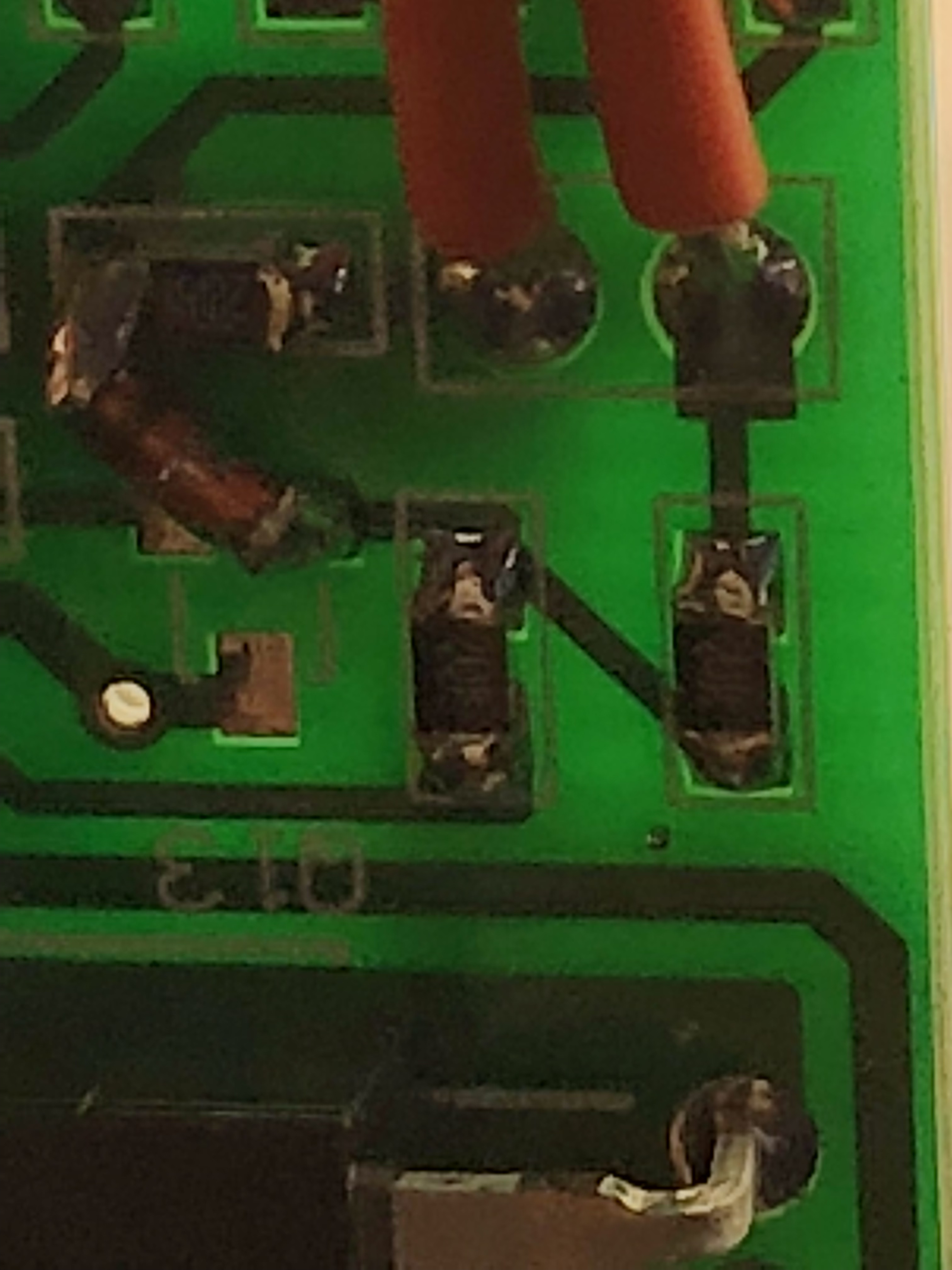
I need the numbers off the resistors. I’m going to try both spots and see which works better

Did you try to zoom in the picture? I can read them very well (the two resistors you marked in your picture). They are 102 and 205.
1 Like
Thank you! I had originally looked on my mobile and it wasn’t working. Tried on my computer and can read them clearly.
I was thinking about this and could you set the vesc minimum input voltage to 10v instead of 8v? Then the VESC would be off and it wouldn’t matter if it was putting out 9v. Also, I was reading on some of the ebike forums that even though some BMS put out a voltage when off, they don’t put out any current and when a load is connected, it drops to 0v.
I just tested this and it´s right. With only the BMS attached I get 3,4V when off. I hooked up the rest of the system, so assembled everything and messured again and it´s only 0,11V now.
1 Like
electricity is so weird.
2 Likes
It´s like water, you have to flow with it
-Bruce Lee 
1 Like
or in this case, its more like my oldest son. Sitting there on the couch with a lot of potential but as soon as i put a work load on him the potential collapses.
7 Likes

10 characters
Same problem, just with the 12S BMS. Has anybody tried the method with the switch on the transistor in the corner with that model?
And can somebody explain to me like I’m five what behavior wiring it like this will result in? Will anything beyond the BMS still be able to draw current when the switch is open? Does the BMS balance cells all the time or only when charging or only when the switch is closed? How does doing this compare to putting a Antispark between the BMS and the Battery or the Vesc respectively? Sorry normally I wouldn’t ask so many fundamental questions and just try it but I want to be extra sure I’m not damaging anything.
2 Likes
I want to know too! 
Me toos Need to know
The finished lithium-ion battery has two main parts including lithium cells and BMS (battery management system).Lithium cell is consists of a positive electrode plate,separator,negative plates,electrolyte.The positive electrode ,the separator and the negative plate would or laminated together ,and then filling electrode batteries made after the packaging.But many people do not know the function of lithium battery protection board (BMS).BMS is to protect overcharge,over discharge and output short-circuit to happen.
Over discharge protection:When the battery is about to run out to a minimum value of the voltage,BMS will shut down the output voltage, and battery can not continue to discharge .Finally product will power off as well.
Overcharge protection:When the product at the time to charge the battery voltage reaches the maximum voltage,the BMS will automatically power off ,showed not continue to charge the full to arrive a protective effect.
Short circuit protection:When the battery is accidentally short circuit ,The BMS will automatically shut down within a few milliseconds ,not power on.Then it will be okay if positive and negative come together.This short circuit protection does not cause an explosion.
Over-current protection:The BMS has a maximum current limiting,and different products are not the same.When the discharge over current protection value,MBS will automatically shut down as well.
Basically the BMS is a alarm system. When a condition gets out of range it sets off the alarm cutting power to the mosfets.
1 Like
Well yeah, that was pretty clear but thanks anyway - what we aren’t very sure about yet is how you can implement a mechanical switch within a 12S Batterysupports BMS.
One proposition was that you would solder the switch to the outer transistor in the top left corner of the board. But even if that works it isn’t known what behavior this will result in (what does it even mean if a BMS is turned “off”?)
- see quoted post:
And can somebody explain to me like I’m five what behavior wiring it like this will result in? Will anything beyond the BMS still be able to draw current when the switch is open? Does the BMS balance cells all the time or only when charging or only when the switch is closed? How does doing this compare to putting a Antispark between the BMS and the Battery or the Vesc respectively? Sorry normally I wouldn’t ask so many fundamental questions and just try it but I want to be extra sure I’m not damaging anything.
If you ever discover the way to make this e-switcg work, you will have to turn the battery/board on in order to charge/balance the battery.
Is it worth it?, not for me at all
sigh, antispark it is
I picked up a Supower 60amp 12s lip ion bms last week. I asked them to install the switch. My hopes were up. Maybe for good reason? Please look at the pics there is an extra resistor installed on mine along with the switch. Fingers crossed  I’m not sure if I will have it together today or not. I like the BMS because of its size.


1 Like
No joy. It didn’t work.
3 Likes
That is very peculiar.
The PCB layout on that should have had a small mosfet or transistor, i’m not sure which, where they put the diode to bridge the two runs. Not sure if that’s a retrofit or if it’s assembled wrong.
I’ve got the same BMS, I’m hoping to be able to retrofit an e-switch to mine. The BMS DOES have short circuit protection, so it definitely has the ability to switch off… I’ll inspect the traces with a flashlight and report back with a possibile solution. I’ll likely tack on some wires, likely onto an existing component on the board so I can artificially trigger a short circuit or temp or over voltage protection.
1 Like
That would be great news. I have already committed to the anti spark. But that could be used in the event of an emergency.