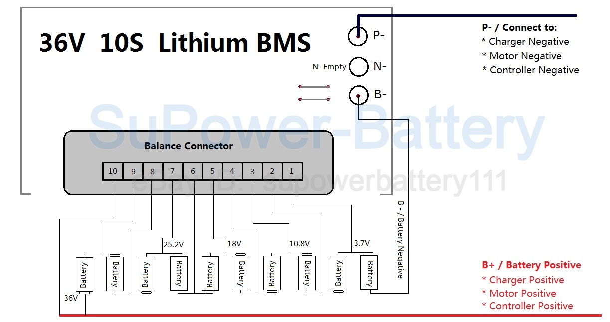
Hi guys, as many of you may know, there’s a group buy going on right now for some batteries in Europe, which is quite a rare thing. Since the manufacturer lets us take a design, and I noticed that many people are asking for a good battery with a bms in a compact form factory, I was wondering if any of you has a diagram (or can make a quick one) for one like this from @denton
I would do this by myself but I know nothing about batteries
Thank you very much
THIS IS NOW A DISCUSSION ABOUT PUTTING A MOSFET E-SWITCH ON THE BMS
I don’t think the bms in the group buy is from batterysupports, so at the moment that’s not a priority, I think. E-switches are cool though, hope it will be possible to have one
The bms itself is an e-switch: it can turn off the battery for several reasons: voltage errors/ amp errors/ temperature threshold…
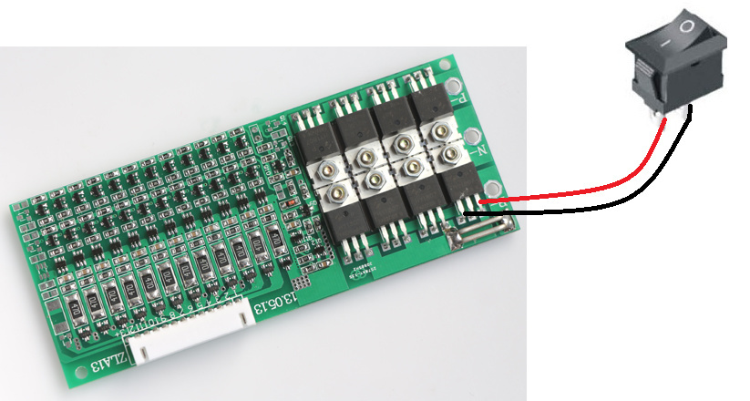
When it comes to add a physical button the options are 2:
there is a spot on the bms board designated to add one on-off switch (like the bms on my thread)
2)You make the bms think something is going wrong: for example you can
short the temperature switch/ fake a failure in one of the balancing wires/…
All the options mentioned work in the same way since the reaction in the board is simply the activation of the mosfets.
Yes, I asked the manufacturer to leave the soldering spots (for the switch) free, so that I can solder an on off switch with a better design (the original was red and rectangular).
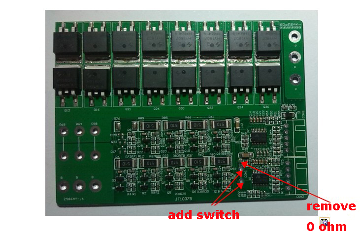
the 2 spots in the circle should be designated for e-switch/temperature switch. If you could provide me with hi-res pictures I could confirm what I am saying.
I will try to explain:
When it comes to print a circut, although the bms company has several models of the same bms (the standard, the fancy one with an e-switch…), they manufacture just 1 type of printed board; all the fancy add ons will be added later.
These 2 spots (see pic) could have served 2 functions:
1)temperature switch
2) e switch
ACCORDING TO THE ONE (function) THEY PICKED, YOU HAVE TO OPERATE IN 2 DIFFERENT WAYS TO ADD YOUR E SWITCH
1)spots designated for temperature switch:
IN THE NORMAL CONDITION, current DOES flow through the temperature switch.
TO GET THE BMS IN “ALARM MODE” (to turn off the battery) you will need to OPEN THE CIRCUIT: remove the resistance next to the spots (see pic).
Could this be tested with a BMS that is not 100% functional. Because someone should with extra BMS’s from prior builds or with a burnt out component should give this a try and let us know because this is a game changer.
 I would do this by myself but I know nothing about batteries
  Thank you very much