A hole saw in a drill press works too.
Bummer - why didn’t I read your thread before? Great solution with these tiny halls - would have saved me several hours and headaches. Thanks!
Sweet build, dude. Incredible documentation.
As for the wheels, I have an idea that might be worth a try. Back when I was a golfer, I used to build my own clubs. They have a tried-and-true way a keep the rubber grips securely fastened to the steel shaft of the club. Essentially they use double-sided tape that adheres securely to both the shaft and the rubber, and a solvent that temporarily turns the glue into a lubricant.
So you pour or lathe your urethane to 1-2mm smaller than the rotor can and apply the double-sided tape to the can. Heat up the urethane with a blow dryer so that it expands just enough to be pushed on. Spray that tape down with the solvent and jam that wheel on while the tape is nice and slick. The solvent will evaporate, leaving the glue which creates a very strong bond.
This method prevents slippage against the torque forces of swinging a golf club; it may work for wheels.
https://www.amazon.com/dp/B00SRGJ53W/ref=cm_sw_r_cp_apa_uCjazbV9RXVWT
Until now I have no issue with slipping urethan - I even think I know why, in the post above I described this in detail.
Regarding pwm (sorry not ppm, parts per million) I meant not efficiency but rather deficiencies/shortcomings. Approximately you have the low pwm / high motor current range at startup and the high pwm / high battery current range at end speed. If you go for constant power you will not be able to get the full available power/performance what your system is able to provide, esp. if you have high power LiPos. PT1 is a term from control theory. Practically this is a measure how fast the motor reacts or how fast he will adhere to the controller input. Benjamin Vedder showed this in one of his earlier videos. The corresponding parameter is “Positive ramping time constant” in the Nunchuk tab.
I don’t know what u mean by going for “constant power”. What u wrote above makes sense abou motor and bat amps. The way I have the vesc it puts out the same 900watts regardless of rpm/duty. I could increase that constant or unbalance it with more power at high speeds or low.
The pt1… Does that change the ramping of power so while the motor/bat amps may be set to something it determines the speed it’s applied after the throttle is applied?
Last chapter:
VESC and Mounting and Housing
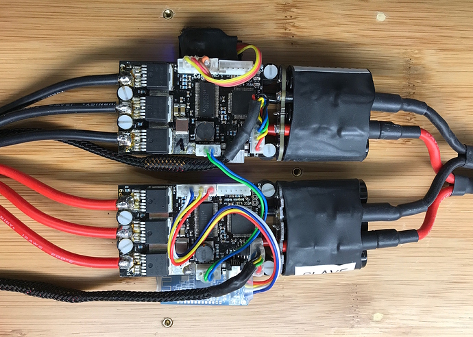
This is not really closely related to the hubs, but it think it’s a good conclusion to the project. Dual hubs, so dual VESCs are needed. I decided to mount the VESCs directly onto the board, for convenience. Since the board has some reasonable flex I put them onto small rubber dampers. The assembly is shown in the next pictures - no words.
I’m a little proud to say that I successfully soldered both VESCs on my own  The master VESC is connected to the receiver for my Nunchuk RF or Kama, the slave to a bluetooth LE module for the connection with the @Ackmaniac app.
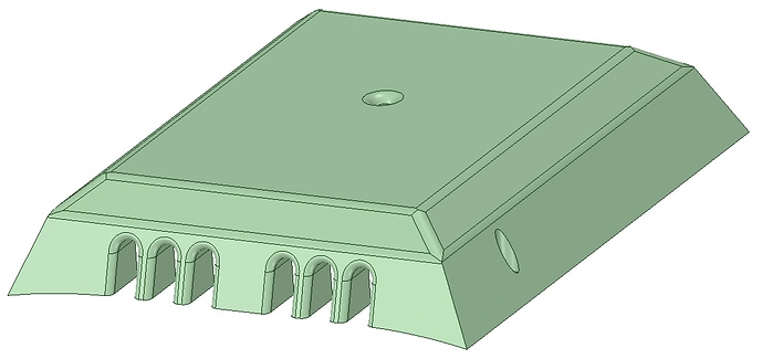
The controllers are covered by an 3D printed enclose, contour crafted to the boards shape.
And this is how the board looks right at this very moment.
Currently I use some LiPos which I reshaped to smaller height, fitted with velcro and three of my puristic Dude clamps. No switches, just an XT90 anti-sparc plug and balance plug. From an aesthetic viewpoint I would love to go for the beautiful lower surface covers and housings of @whitepony. We’ll see … I already looked for some fancy vacuum pumps and epoxy resin tools  . LiIon batteries are also on my list. My spot welder is already made and ready for use - but that’s another story.
The link to the 2D-drawings is now added to my first post. Thanks for reading!
that spot welder looks really familiar 
True, true 
[quote=“Hummie, post:54, topic:21519, full:true”] I don’t know what u mean by going for “constant power”. What u wrote above makes sense abou motor and bat amps. The way I have the vesc it puts out the same 900watts regardless of rpm/duty. I could increase that constant or unbalance it with more power at high speeds or low. [/quote]
With constant power I mean exactly what you said, e.g. 900 watts regardless of rpm/duty. I prefer to go for the maximum (to be honest, almost) for motor, batt no matter if this reveals different watts for different rpm/duty and adjust the behaviour by max_watt and the shape of the throttle curve.
Suppose according to your joystick deflection (watt or current mode) you are traveling in a steady state. Then, you suddenly pull the joystick further for some amount/degree. The parameter now determines how fast the VESC is aiming to reach the new state you are demanding through your input. You can experience this very easy, while putting the board on the bench and observe what happens when you quickly move the joystick, depending on the value you’ve set. When I remember it correctly the default is 0.9. If you set it e.g. to 5 the response of the motor to changes is more smooth.
I was contemplating soldering my own vesc as well. Did you start from a semi assembled board? Any pointers you can give (such as where to buy a quality pcb board)?. Is it doable with a soldering iron (soldering station with adjustable temperature) or do i need a reflow station?
Man, upload more videos, your work is just amazing
I ordered the pcb’s from oshpark and the parts from mouser. You need a soldering iron with temperature control with a very fine soldering tip, fine tin, flux, SMD hot air station,
SMD soldering paste … and a mircoscope or a real goog magnifying glass to control what you’ve done.
Where did you get those tiny hall sensors?! they are fantastic!
What do I have to know about hall sensors? Maybe I want to put them in jacob’s hubs. I would have an old RC motor (4s) with hall sensors. Could I use them or do I need special hall sensors?
Is there any chance You could upload those drawings in higher quality?
The link to my dropbox is already in the first post. Gimme a notice if you can access the drawings.
Thanks! Downloaded the files, everything looks great!
Thank you for opening this thread.  Nice to see that there are also some “real DIY” people out there. This build rocks. Do you have done some real world testings since your last update. Would be interesting to see how they perform compared to your belt drive system.
And are there any infos available about your spot welder. (I remember to saw @whitepony’s similar one somewhere, but maybe there is a extra thread somewhere that I haven’t seen) Thanks. Keep up that awesome work.
mine is here: https://endless-sphere.com/forums/viewtopic.php?f=35&t=70435#p1062504
good old days 


