For those after a smaller size, I am considering modifying the layout and putting the cell balancing on the bottom of the board, 140mm is a little too wide for my build. If I do it, I will post the modified files so others can build the smaller PCB.
I dont see why not. As it stands the DBMS is large but people still use it for its functionallity. That being said, 160mm it a bit long, as even something like @Eboosted DS enclosure is about 152 mm (i think, Alan? how far off am i?) I think you might be able to get away with trading the length for thickness, producing someething like a double pcb BMS that could be stacked or something.
OH! That makes me wonder, whats the feasability of having a charge only bms module (small) that could be upgraded with a high discharge portion, depending on the need of the user?
Just looking for the mechanical limits  . 160mm are 8 times a 18650 with 20mm center to center, that’s why I thought it would be reasonable.
Yes external discharge switch is absolutely doable but complicate dings a whole lot when explaining and debugging. I am not super negative, just sceptical…
1 Like
I think skepticism is appreciated, especially when talking about something where you clearly have more experience. Maybe 160mm isn’t that absurd, and i think at the end of the day it would depend on the way that the final product is designed that will dictate wether or not it would make sense to use. I would like to imagine a system where the bms and VESC are both mounted on a heatsink(s) and are easy to integrate, so, would love to see what you have in mind either way!
Was there ever a full manual and diagram for this written up? I’m about to wire it all up to the new battery I’m making and want to make sure I’m doing it 100% correctly.
I’ve found various pictures of people drawing out how to hook up the switch and the charging port, but still didn’t see an official manual. (or is it all just the info thats posted throughout this thread and I need to extract it?)
Also, this is my first ever BMS that I’m wring up so I’m a total noob here.
2 Likes
So not too much need to be done to wire it up. I’ll see if I can compile a quick guide here:
First, easy enough to wire up the power switch and screen
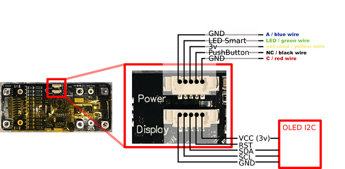
Then the balance plug is simple:

If you want to use temp sensors, which btw I think everyone should since it’s implemented and a huge safety feature, then connect 1 side of the temp sensor to the gnd, and the other to t1. For the second temp sensor, again, connect 1 side to gnd and the other to t2. Remember, temp sensors are variable resistors. So as they heat up, they change their resistance and the BMS simply measures the resistance to figure out what temp it is. Pretty nifty, eh?
If not using temp sensors, leave gnd, t1, and t2 empty.
If you need temp sensors, I’m using these: https://www.amazon.com/gp/product/B06XR1TG5N And if you need wire’s pre-crympt, I’m using these: https://www.mouser.com/ProductDetail/710-662100124015
Then, the actual wiring:
Pack + -> Positive of the battery Pack - -> Negative of the battery Charge + -> Positive of the charger Load + -> Positive of the VESC or other ESC (You’d better use a VESC shakes fist in anger) Common - -> Negative of the VESC or other ESC AND negative of the charger
For the canbus, here’s how to wire up with the vesc:
(Please note, CAN H and Can L are the center 2 pins of the VESC CANBus Port) (on the 4.12: CAN H is the center pin, closer to the FETs, and CAN L is the other center pin, closer to the big external caps, 5v is the pin closest to the FET’s, and GND is the opposite side)
All Vesc’s CAN L -> BMS CAN L All Vesc’s CAN H -> BMS CAN H 1 Vesc’s 5v -> BMS 5v CAN AND Enable Can (Enable Can is for push to start) All Vesc’s GND -> BMS CAN GND
By Default, The ID of the BMS for CanBus purposes should be 10.
That should be everything condensed into one post that should get you up and started.
24 Likes
Awesome, yea having it all condensed here makes it alot easier!!!
Thanks so much man! I’m excited to get this going and running.
1 Like
As am I, haha. I still haven’t done the final wire up or the balance plug. I had a nightmare getting those pins crympted for the balance cable’s port, so I ended up ordering some from mouser pre-crypmt.
If anyone has the same issue, here’s a link to ones that will fit (I’ve already tested and confirmed they are a perfect match): https://www.mouser.com/ProductDetail/710-662100124015
1 Like
Ah crap, I forgot about that. I wonder if my regular crimpers will work. Or maybe I’ll just buy these.
Trying to use crimpers was a nightmare for me and I couldn’t get them all the way in.
I found their shipping was very fast. But the wires are complete shit IMO, not a good soft silicon wire. But it should get the job done.
I may still have my old crimper for old serial connectors, it would work, but not sure if I still have it or not.
Oh well, small issue in a bigger adventure!
On the topic of crimping the balance cables. I used a crimping tool for AMP MODU IV contacts that I have access to at the place I work at.
 the WR-MPC3 contact is very similar to the AMP MODU IV crimp contact on the wire side.
WR-MPC3:

AMP MODU IV:
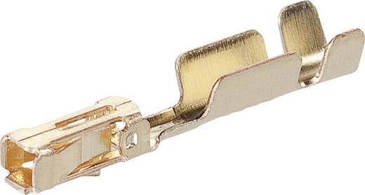
It worked quite well so I thought I’d share my experience.
3 Likes
Since this thread is about the DieBieMS and my DIY battery uses one I’m gonna ask here.
I build my pack a few weeks ago. The rest of my project (not a skateboard, I’m putting it on my scooter) isn’t finished so I can’t use it yet. I have it sitting on my desk, do some testing and configuration changes with it and my vesc from time to time.
Today I turn it on and got the battery with an X on the display. I immediately checked the pack voltage but it dtill was at 41 volts (pack is 10S3P). So I connected it to my pc and fired up the DieBieMSTool to check the individual cell voltages and I see this:

C3 and C5 have dropped quite a bit and I have no idea why. Anyone here has an idea? I really hope I don’t have bad cells. I really don’t want to have to take the pack apart and search for broken cells. The cells I used are new LG HG2 18650.
1 Like
I would definitely say bad cells. Most likely 2 bad cells in c5 and 1 in c3
This can be caused by several things:
- One or more cells in your parallel group of groups (C3 and C5) got disconnected for some reason and now those groups have a lower capacity, therefore discharged faster and now have a lower voltage.(medium bad because now you have to reweld them / resolder them). I had exactly this happen to me but than with a single group multiple times (I wasnt skilled at welding yet), but because I have a 6S4P pack and only discharge slowly I only noticed it when my board cut of (by the bms) instead of throttling back (VESC), but one will only notice that when you have it configured correctly (the VESC) and use the board often.
- some of your balance leads came lose and therefore the reading of the BMS is wrong. However normally when this happen two cells right next tho each other have a strange reading instead of in your case where two readings are wrong with a healthy in the middel, therefore I think this isn’t the case.
- Some of the main current carrying connections between the parallel groups opened resulting in large voltages across the cell balance inputs of the BMS (this could be bad). This is very annoying to debug.
Some things you could do to diagnose further:
- Measure the parallel group voltages individually on the balance connector.
- Measure the parallel group voltages on the batteries directly (but be sure not to accidentally apply pressure on the nickel that cause a broken weld to attach to the cell again , I say thay because I had that trap for young players happen to me more often than I prefer
 ).
). - turn everything on and try to load the system a bit by slightly running the motor, if this works the connection between your parallel groups are likely to be OK.
2 Likes
Thanks for the replies.
I checked all welds and balance lead connections and they seem fine. Nothing looks or feels loose. Measuring the cells in question directly on the nickel strip, I get 3,72V on C3 and 3,19V at C5. Just like the BMS reports in the software.
The pack was never in use so it didn’t experience any mechanical stress from vibrations. Highest electrical load was 3A maybe 4A max. from spinning my motor without any load.
Should I just try to charge the two p-groups manualy and see if they discharge on their own again?
Good idea! Try to Balance the Pack manualy and inspect it carefully. It is worth a try before you are going to disassemble sth.
All welds are ok and the battery isn’t used? Are the cells used or reused? Was it balanced when you assembled them?
If those two cells groups discharged themselves this could be because of bad cells ( never happens two times in the same pack ), or the BMS got damaged and is now leaking current ( can happen when you connected it wrong and fixed it later ) or the BMS was faulty from the start. I have only seen this happen once in maybe 50 boards, but then only on one group and not two.
1 Like
Cells are all new and arrived with 3,5V. After assembling my pack I was at 35V. I double checked all balance leads both physically and electrically before plugin in the balance connector. The only mistake I made was not plugging in the ground of the balance connector but after seeing a to low voltage on C0 in the tool I fixed that. Afterwards I charged it with 42V and 2A till it was fully charged.
I’m gonna charge the two p-groups manually and see if they discharge on their own again. That way I can rule out the BMS as the problem.
That all sounds good and you did all you could have done. You could indeed charge them and measure with a couple hours intervals whether they are discharging.