The firmware can be found here:
First erase the chip, Pick the default firmware and flash it, and when communication works with the BMS be sure to upload the bootloader with the BMS tool for the next firmware update with the BMS tool.
The firmware can be found here:
First erase the chip, Pick the default firmware and flash it, and when communication works with the BMS be sure to upload the bootloader with the BMS tool for the next firmware update with the BMS tool.

We are doing tests with it, but 150A is ALOT, and are still improving.
So I used st-flash erase, then st-flash write DieBieMS_default.bin 0x08000000, then unplugged the debugger and plugged in the USB cable.
It shows up, but I’m still getting No firmware read response, regardless of whether my battery pack is connected, whether the debugger is providing power or not, nothing. Flashing or not flashing the boot loader to 0x08032000 makes no difference.
Do you have any other debugging steps I can try?
If you look closely at the second picture it is a DieBieMS with the more amps shield.  So it’s still up in the air about just the DieBieMS. Though heart pumping to see the elusive more amp shield in the wild
Does the LED blink a couple of times?
Did it ever work or just suddenly stop? I believe that every thing including the usb was tested during the production, so at some point it should have worked.
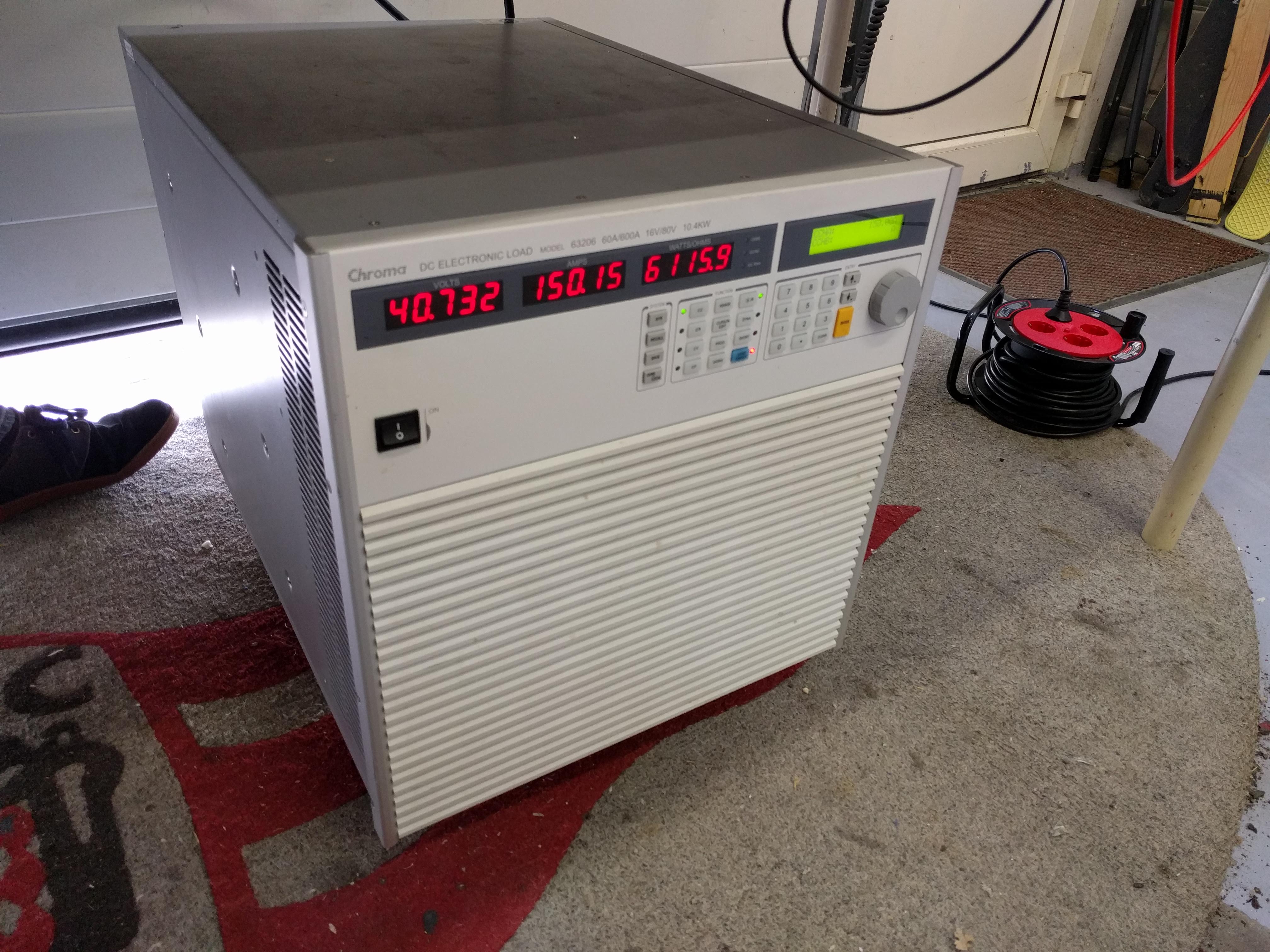
Yes it is doing 150A but only for 15 minutes ( then the temperature raised to 70 degree C and the battery itself became warm and we stopped ).
But at 150A and 15 minutes the battery was also almost drained
Hallo @JTAG, just curious if you did consider to build a charging only BMS with very small footprint, smart enough to work with metr.pro? Dank u!
It always worked, I had it in my board for a few months, but wanted to set up CAN forwarding, so I disassembled my board and hooked it up only to find it no longer connecting. It still charged, and discharged correctly, until I flashed firmware (but that is most likely due to the default being 10 cells not 12). Now when powered it slow blinks, then after a while goes off with the second LED always remaining lit. Neither LED turns on when only connected via USB.
@JTAG Ahhh great to see you still around and testing the more amps shield. Do you not recommend trying to do more than 80 amps then with out the more amps shield?
I’m tempted to get that 125 amp fuse and see what happens. If it’s a bad idea, would love to be told off before I blew it up, haha.
Anyone by any change got the dimensions between the four mounting holes on PCB?
@JTAG, I’m wondering how the bootloader is programmed onto the device in the first place? Do you purchase the chips preprogrammed?
Yeah, the pattern is 90 mm x40 mm measured from the centres of the holes which should have a diameter of 3.2 mm. in case you wanna know more dimensions and you haven’t seen the link, here’s the Github link for the 3D files. I also double checked the dimensions by hand and it’s correct.
They are programmed trough the SWD debug connector on the bottom, when DIY assembling you have to do that yourself. You could first flash the main application followed by the bootloader either trough the DieBieMS tool or directly with the debugger. Notice that this bootloader works different than the arduino style bootloader (the BMS has the same style as the VESC).
I am thinking about designing a small and compact one, but that is still a very long time away… What functionality would you like to get rid off? only discharging or would you also accept slow balancing?
@evoheyax As a very short pulse it might handle it, but not sure for how long  . I could to a small test and film it with the Flir and webcam, I do have to find a suitable battery and wiring trough…
@Joon Thanks! We sould put the mechanical drawings in the manual as well :…
How far off…  Like how could we get you to design a compact bms that could be suitable for high discharge. Like we need something like the DBMS but higher discharge, even if it sacrafices the size a lil.
What do you think? Do we need to hire you?
That’s a good news!!! Thanks
For what most I would like it is for monitoring with metr.pro, if it’s doing also balance even better, doesn’t matter if is slow balancing.
For my liking it will be 10s-12s, charge around 4-5 amps, UART, balancing and small, kind of 3 or 4p 16850 size.
Thanks !!!
5A 12S should be doable, will look into it next year, I won’t be promising anything . Some things just might need to go, and be a little less fancy… this might suppress the cost and benefit size. But enough projects for now  .
.
For a small footprint high discharge BMS would you accept a narrow but long (30 times 160mm) BMS that needs to be mounted on a strip of aluminium? What would be an acceptable method of mounting the wires (avoiding press fits)?
Ahh thanks, I missed that connector in the schematic.