Littelfuse bf1 58v
5 Likes
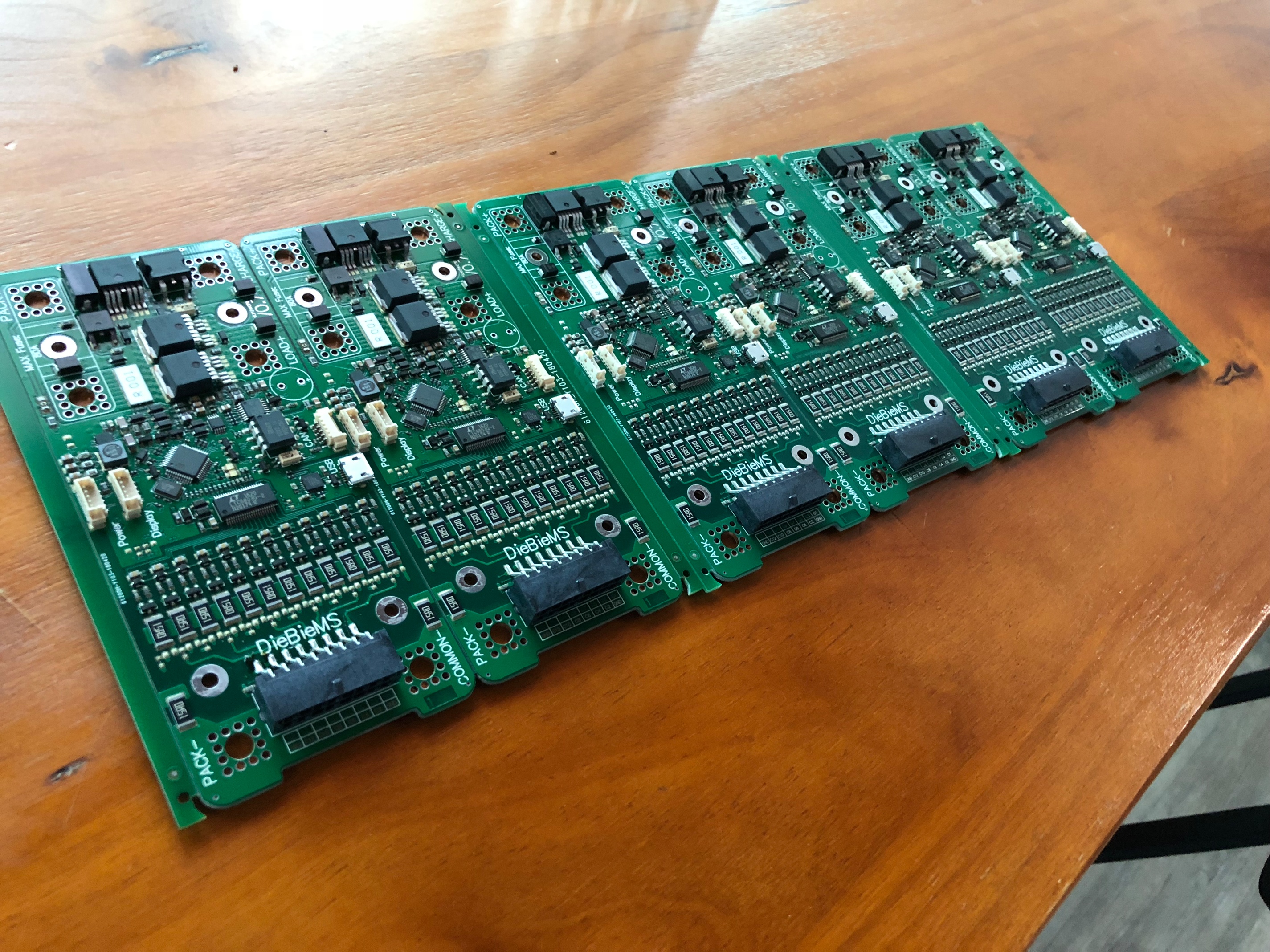
Could you elaborate on wiring? Most protection boards and BMS’es i had would have a negative, charge negative and load negative + sense wires going to BMS/PCM. This one has like 5 power connectors. Are they all need to be connected or say pack - and common - are the same? I would like to fit it to my modules but i have 4 power ports.


Thanks
2 Likes
Load+ and common goes to vesc(s)
Pack+ and pack-(Linked to common internally) goes to pack. *so you can save a cable opening, but will gain some connector height total height. Worst if you are using two packs.
Charge+ and common to charger.
You will also need the sensor/balance, canbus(s) , display and power connector to be exposed.
2 Likes
@jtag, great design imo, just ordered one from @Samau18 
I do have a question, how is an overcurrent (or other error) handled? The most obvious way should be disconnecting the load. but in that case the VESC is powered down and (on a esk8) you would be even unable to brake.
What if the error could be handled by telling the VESC to limit or cut the power/throttle gracefully before cutting the load completely in a specified amount milliseconds?
Of course current and temperature thresholds should apply where the load is cut of anyway
Was going see if @jtag would answer it, but seems like he is busy. I would say you should always set some margins (VESC max current + safety margins = BMS max current), so the VESC can still have power to handle before the BMS is at it’s limits.
1 Like
Guys a quick update. Still setting up SMT machine, I am pushing for completion asap. Will update again when I start testing.
2 Likes
Ring terminals with a 90deg offset make this ok I think
That’s correct.
Waiting on the loading resister still. Should be here soon. Will flash firmware later today.
12 Likes
Beautiful! 
Gonna throw some questions out that I didn’t see solid answers for in the original thread.
I saw in the original thread @JTAG said charger should be 3v higher than pack max voltage. So for example 12s full is 50.4v. We need a cc/cv source at 53.4v? This is not typical, and means we cannot use 12s bulk chargers? Am I misunderstanding something?
Does anyone know what happens when limits are hit? Like cell or pack overvoltage when braking?
And are heatsinks necessary with say dual 6374 with like 12s4p or 10s5p riding it with spirit? I think its borderline?
2 Likes
Well it depends.
It all has to do with the power on state of the BMS. The BMS is designed such that when not used for an configurable amount of time it will turn off to a state where the microcontroller cannot recover out of on its own. In this state, the normal “off” state the BMS will enable by any of the following external events:
- The power button is pushed.
- 5V is fed into the usb port (a computer is connected to the usb port).
- 5V is applied to the can enable pin on the can connector.
- the charge port input is 3V higher than the pack voltage.
So if you want the convenience of having the BMS to automatically turn on when a charger is connected then the charger (CC/VC) voltage should indeed be 3V higher than the pack voltage.This is how I use my BMS in almost all applications.
But recently however I added the (configurable) functionality to allow charging during the normal (discharge enable) state. So if you have a charger that has a voltage of 0.6V (charger input diode drop) higher than the battery voltage then the battery wil charge as normal without the need of the extra 3V.
If you also want to get rid of the diode drop of 0.6V you can bridge it by putting a solder blob on these pad’s:
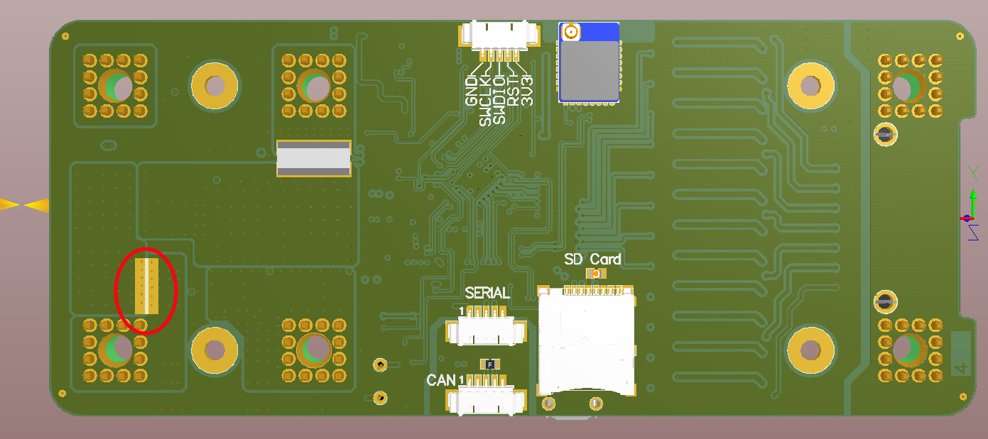
But be careful when doing this! When you bypass the charge input diode you can discharge out of the charge input due to the parasitic body diode in the charge FET. So male charge connectors will become a no no, the charger will be energised when attaching it with the connector (will spark due to the output caps of the charger when the charger has a lower voltage than the battery on its output).
5 Likes
Wow, thanks for the detailed explanation. I’ll try to read code for the rest, maybe learn something. Really excited!
No worries, need to write a manual as well and therefore I can reuse what I write  .
.
4 Likes

Arrived!
10 Likes
what is it? some kind of mega wirewound resistor?
Is a huge resistor to simulate 4000w loading. 50v*80A. Quick testing of the boards before I sent them out.
Sam
8 Likes
fine piece of kit
quick video plz… omg lol.
1 Like
The torture  .
.
4 Likes