not percisely calculated but around 1200€ with Charger an everything.
1 Like
Not digging the proof, just really interested how you get those esc set up with that settings running stable. I have two of them as well. One fucked pretty fast after some over current faults I still can’t explain where they where coming from and after that I run one in single at 40A bat max which took me exactly 2min till the esc shut down because of over temperature. The broken one is on repair at the moment and I really would like to use them on one of my other builds, but if I can’t even run them with 40A bat max it will just not work for me.
So what you would recommend. Change the heat paste to other one and mount the vescs on a bigger heat sink?
are you using the esk8 vescs with direct fets? The 1.7mOhm direct fets? Because the hardware I use is basically somwhat of a VESC6 when it comes to the mosfet / capacitors at least. I also blew one up on an eBike that had almost no thermal paste between the pads and the case. I also set the slow maximum amps to 150A for this experiment with 90 motor amps. They ran fine for almost a minute on 70A foc_openloop and for around 10 seconds on 90A openloop before throtteling down. But never any errors just cutting down the amps.
1 Like
So you set 90A battery in each vesc? You can do what you want, but the data sheet exists for a reason
You are heating each cell at 40W, at that level, even just a peak has the potential to take the core of the cell to a really high temperature, there is not enough conductivity for the heat to flow out
If you manage to do some logs of acceleration from dead stop, maybe in a heavy hill I would love to see if you manage to hit the 180A
1 Like
I have this one

2 Likes
jupp thats the one I used too. On the mosfets put some good thermalpads like the EYGA series (A is important because they are not conductive) like the EYGA091203A for example on there and add some good thermal paste on top and this thing should easily get 90A as long as the metal is cool
2 Likes
Sorry Leo, i ve seen your vid again and saw you finally spot welded your batteries. It was on your first build you soldered them. My fault. peace
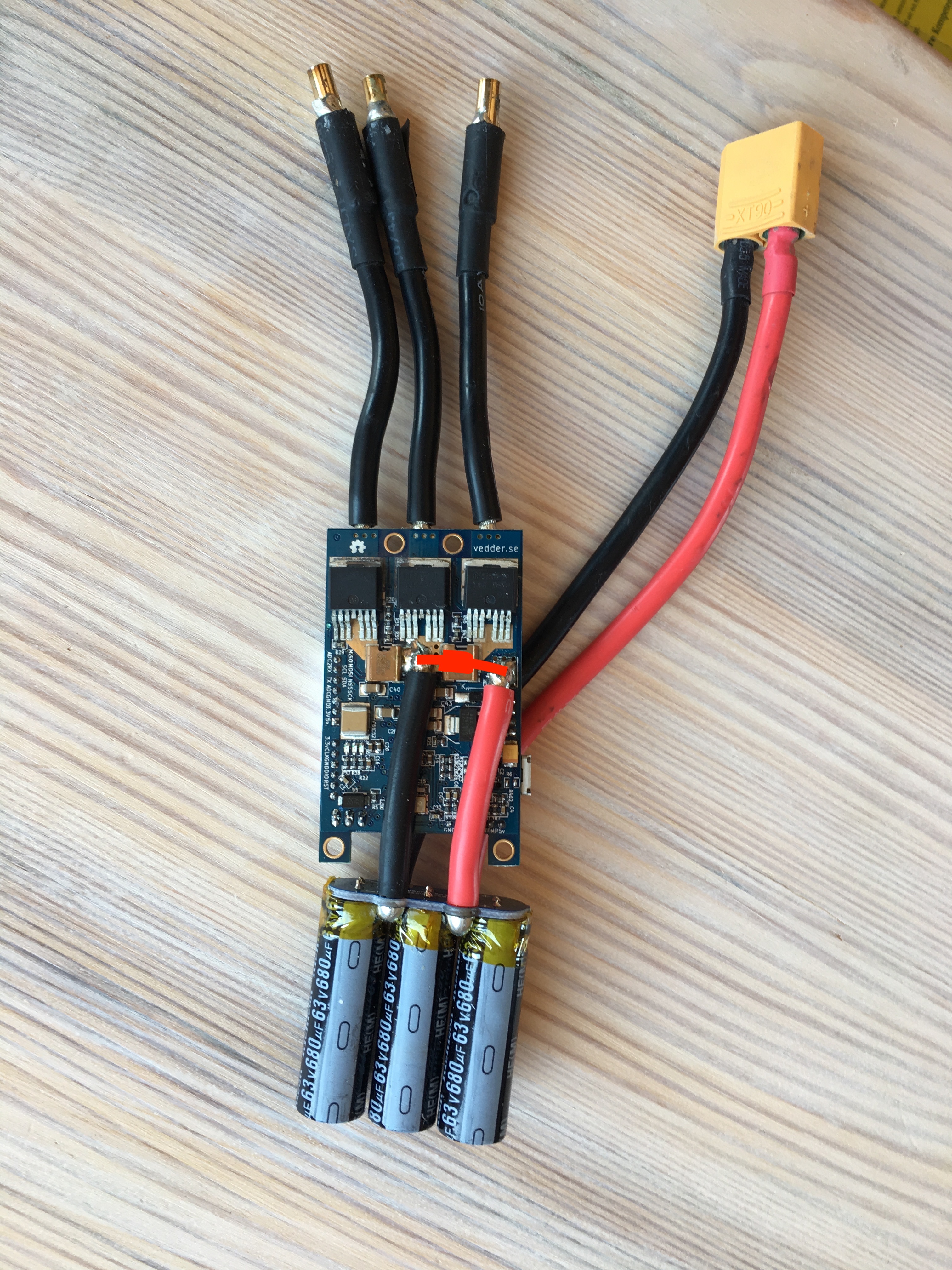
Can please someone confirm that I have to solder the TVS Diode there, see picture? Or does it goes on the other side, where the cables from the batterie are?
1 Like
Hey i saw you would see the pre change anti-spark circuit for €30. I was wondering how i could message you about this.
I would like to start getting everything ready to make something like this during the year.
Just wondering, the TVS diode is supposed to be reversed biased? Does that mean the voltage spikes / surges are opposite polarity? Or is it in forward biased with respect to the battery polarity?
Edit : does that also mean that if I choose a bidirectional one, it’ll constantly drain the battery?
Just use a loopkey…
Hello, if I am using 2 ESC, do I need to use 2 recievers?
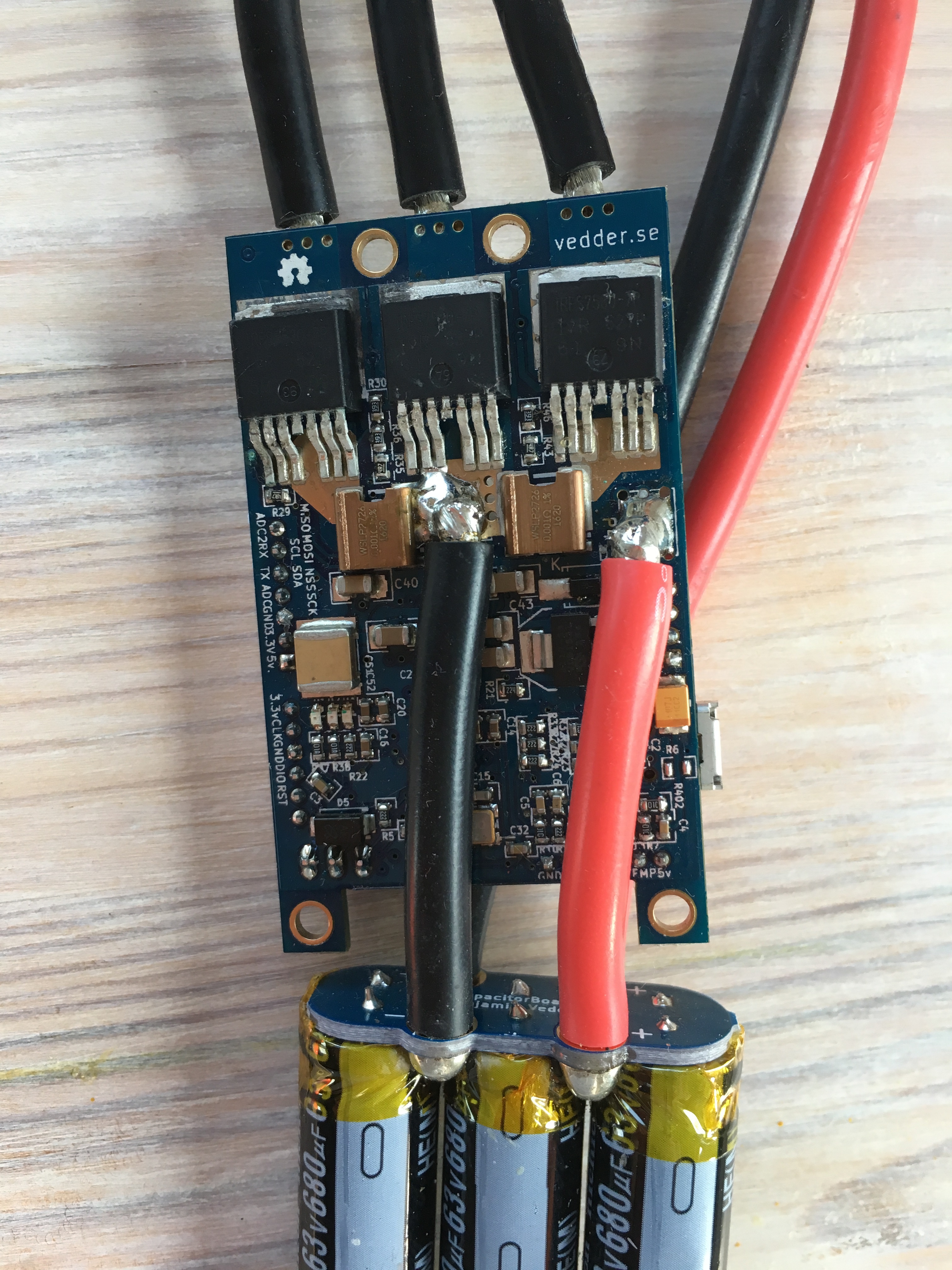
Could you please take picture from the other side?
no, you can solder the wires coming from the two vescs in parallel to one wire going into your receiver. It will work
Thank you sooo much.
1 Like
Do you know where to find schematic how to use UART port of flipsky ESC with arduino? It is my first time using Arduino, so I do not really see it in code files. On https://solidgeek.dk/docs/firefly-remote/receiver/schematic/ webside it is connected via 3 pin servo connector (writing to ESC)
Thanks for having a look at the pictures. Its the normal 4.12 TB VESC.


I personally use the ppm port of my vesc with a rc remote. Are you going to build a firefly remote?
If anyone needs this printed. I have a large fully enclosed printer that print this without issue.
My setup is posted below.
1 Like
yeah, I already builded the transmiter… I have got a problem with this UART port