Thanks for the advice. what about height off the deck with jst ph plugs in? I guess the only way to provide easy access to the usb because i am running two would be to run them long ways and not side by side. Do you typically mount the vesc directly to the board?


Nice ! Thank you very much, I m looking forward to receive it !
On another forum, a guy noticed the UART port has now 7 pins. Does anyone know how to wire the Nyko Kama dongle in this configuration ?
Nice ! Thank you very much, I m looking forward to receive it !
On another forum, a guy noticed the UART port has now 7 pins. Does anyone know how to wire the Nyko Kama dongle in this configuration ?
Can anyone answer this? I bought the 6-pin connectors thinking that would be good enough. Its a good thing I didn’t solder them to the Nyko Receiver yet. What kind of connectors do we need now ? Is this what we need: http://www.ebay.com/itm/JST-2-0-PH-7-Pin-Female-Connector-with-Wire-and-Male-Connector-x-10-Sets-/121367876323?hash=item1c4216d2e3:g:OvoAAOxyKsZRy55z ?
Hi mate, you don’t need a 7pin connector, I use a 6pin connector still, the end pin is 5v don’t need it,

But the extra pins are for connecting a nrf24 chip not the nyko kama so you will be fine any way.
1 Like
I have 7 pin connectors. I am going to make some adapters with the Nunchucky breakout board if anyone is interested. I’ll have a listing up in my online shop soon.
@jacobbloy : thanks for the answer, it’s a relief  @chaka : For now I have the Kama dongle, but apparetly it may loose connection so I will probably check your website.
You still use the dongle, it just makes it easy to connect the dongle to the vesc. If you have some soldering skills it is best to solder directly to the dongle’s PCB.
Thanks for the info. I don’t know much about connectors, so all 6 pin JST-PH connectors should fit the 7 pin socket right, they are standardized ? This is the one I have 6 pin JST-PH 2.0mm connector housing wire header 30cm receiver board PCB 25 set | eBay
Just wanted to verify before i solder it.
@chaka : Ok I got it. For some reason I thought the nunchucky was a different brand of wireless nunchuck. But in your opinion is it realy hard to solder the dongle directly to the VESC? Do you solder the thin dongle wires that are already there ?
Correct that is right
You can, it is really personal preference. I like to use connectors first and once it is confirmed as working I then solder it in
Yeah I like that idea. Test with plugs and then solder. I wouldn’t run a skateboard with plugs or adapters because it’s just one more point of failure added to the mix. None of this stuff is designed to withstand the amount of shock and vibration of skateboarding.
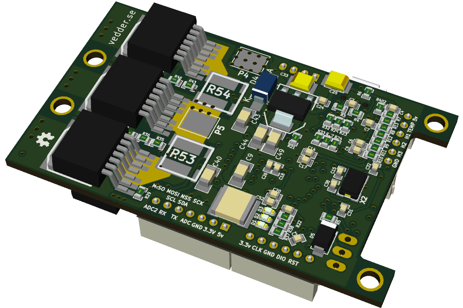
Hey @jacobbloy @chaka or anyone, can you tell me if the diagram from this guide is correct ?? Looking at the VESC pinouts i think it might be outdated now? http://www.electric-skateboard.builders/t/vesc-faq-connect-the-nyko-kama-wireless-wii-nunchuck/139
Here are the VESC pinouts https://raw.githubusercontent.com/vedderb/bldc-hardware/master/design/PNGs/3D_back.png
the 3 bottom pins ( left most in the diagram ) are ADC2,RX,TX while the forum thread guide shows them as RX_SCL, TX_SDA, ADC_EXT
Is the guide outdated ?
Thanks for confirming. That is what it looks like to me as well. @jacobbloy’s comment confused me since he mentioned the 5v
so @jacobbloy must have made resoldered a new connector for 4.10 ? If he was reusing his old 6-pin theres no way that position in that photo would work right ?
*edit I just took a look at some of the older diagrams and the schematic on Vedders site and it does look like you are right, the pinouts are the same with the addition of the ADC2
crap i just noticed my Nyko Kama receiver doesn’t match the one from the guide either… have any of you guys seen this variant of the nyko kama receiver?
*edit nevermind I found a diagram of the wii socket pins and was able to map this version of the nyko kama to the correct pins

I was simply demonstrating that the 6pin plug works if the wires don’t match you can do a pop and swap of the wires in the plug.
ah i see, that makes sense.
Do you have a source for that pinout ?
I actually have the little converter pcb thing in this post:
So that labelled the pins for me before I cut the wires to the head.
Heres a random diagram from google images that seems to be consistent with the convert pcb thing:

Keep in mind this view is looking at it from the front. When you look at it from the back ( the part will you will cut the wires ) the left and right will be opposite.