Ok yea definitely looks like that could be the fault
Thanks for taking the time to post such a comprehensive and entertaining log!
Might also wanna try different bushings for your trucks. Lots of different shapes and duros to tune it to preference.
Thanks Steve, Appreciate that
Cheers DP. Are they pretty much universal?
Took a short video clip of a couple of trips around the block today so you can see it in action.
I kind of imagined my first video being shot on a hot sunny day, with some exciting background music, but that little fantasy is six months away here in England. ![]() Ah well here it is. Watch out for the leaf action at the end…
Ah well here it is. Watch out for the leaf action at the end…![]() …I know, grow up!
…I know, grow up!

3 Likes


just read every word from top to bottom. What beautiful craftsmanship, such sadness and tragedy, then a happy ending. Bravo sir, bravo
Great thread. Good to see more guys in the uk! What deck is that then?
Cheers M, nice of you to say.
Thanks Vince, £20 ebay special for a complete board. No maker’s name.
Rock solid! However watching the video i keep noticing the noise… Is it really that loud?
Cheers Mark.
I think it’s just the fact that the GoPro on a stick is a mere 2ft from the motor/ground etc.
Seems fine from 6ft up, where my ears are.
Knew I should have gone for that music. 
1 Like
So…I’ve been using my creation for a couple of weeks now and it’s been running very well. Time for some upgrades.
I stripped down the drive system and noticed that the wheel bearings in the driven wheel had become a little loose in the wheel hub. All the other wheels were fine so I put it down to the belt and pulley system putting a substantial amount of twist on the wheel during acceleration and hill climbing. This seems to have eased the hub a little. The bearings aren’t really loose but they do now slide in and out more easily than the did when I first assembled them. I could see that an extra, larger bearing located withing the drive pulley would completely eradicate the undesirable twisting and make for a very solid drive system. I machined out the pulley to take my chosen bearing and machined the hanger so that it would slide on nicely. I didn’t take any pictures at the time as it was a fairly quick job and I got excited to try it out. So here’s a crude sketch to explain what I’d done.
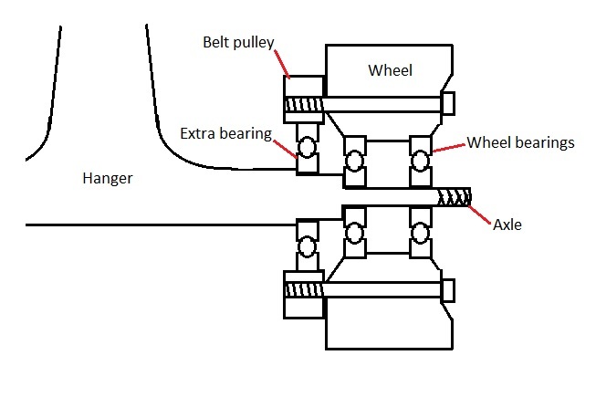
Now this was another one of those ideas that I thought was previously unknown but, after some searching, I see that a couple of esk8 builders have done it. Anyway, it runs very well and I reckon feels a little smoother, especially under heavy acceleration from low speeds. I’ll take some pictures next time it’s stripped down.
More soon, Andy.
2 Likes
Hope everyone had a good Christmas and all the best for the new year.
I had my esk8 drive wheel apart the other day and took some pictures of the additional bearing installation and the drive pulley attachment parts which I haven’t shown previously.


So, what next?
The GT2B Mod of coarse.
I love the reliability of the GT2B 2.4ghz controller so what to do to miniaturise it?
I settled on the 3D printable Badwolf V2 by bjornw and made available to all on thingiverse here http://www.thingiverse.com/thing:922378
I downloaded the print files and took them to work where we have a couple of well used 3D printers. It took a few attempts to successfully set up the printers and get the job done but it was rewarding in the end.
The finish isn’t as good as can be attained with better printers but seeing as I’ll probably drop it multiple times, I’m happy with.
I had to cut a couple of millimeters off the edges of the GT2B printed circuit board with a junior hacksaw and file it neat.Triple check the PCB tracks to make sure nothing was damaged and no shorts created.
I de-soldered the USB port and re-connected it using servo wire. The GT2B on/off switch is of fairly low structural quality so, in order that I don’t have to use the Badwolf switch knob extension, I de-soldered that too and reconnected it with servo wire. This allows the switch to be hot glued directly to the case and makes switch operation feel much better.
Other than that, every thing is pretty much how most people have done it. A few blobs of hot glue and all held together with four of the original GT2B case screws.
Many thanks to bjornw.
Here’s the pictures.


Thanks for reading, more soon.
3 Likes
Did you buy the electrical components for the Gt2B?
Hi WMJ,
I bought a complete new GT2B. They are only about £23 delivered. Used it for a while then dismantled it and used the components for the Badwolf conversion. Apart from a couple of M3 screws, nothing else is required.
Andy.
1 Like
Oh so your remote is just a Gt2B except taken out the housing and put into a smaller form factor. This makes sense now
That’s it.
So…as they say…I’ve been charging my skateboard with my trusty Fusion LX60B.
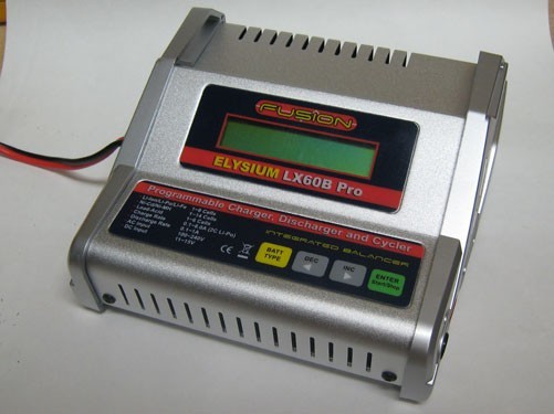
It’s a great charger and I’ve been charging my 3s and 4s drone LiPo’s with it for some years. It’s only a 50w charger though and although it will charge one of my 3s 5000mah LiPo’s in about an hour, it’s got it’s hands full with my 10000mah of 6s LiPo in the skateboard.
It charges them fine but as it can only maintain around 2A max on a 6s pack, charging can take up to 4 hours if the skateboard needs a full 8000mah putting in.
So, I’m ready for a more powerful charger. At around £60, I really couldn’t resist the fairly new iSDT SC-620.

It’s a 500w charger so easily manages a solid 10A on 6s packs, which is what I want to charge at. It will sustain a whopping 20A on 6s if one were so inclined. Seeing at my 6s pack is effectively 10000mah, I’ll stick with 10A which represents a 1C charge rate and delivers the required 8000mah in around 48 minutes.
The only thing is, this charger requires a power supply, ie, it’s not built in like my old Fusion charger. No problem, time to get involved with converting an old server power supply to use as a power source. There’s lots of info on converting these but the Dell units looked well documented and straight forward so this is what I chose.

This is the Dell Z670P and is rated at 670W continuous. That’s a thumping 54A at 12v!
Units like this are being churned out on ebay for really low prices. I picked two of these up for £13 delivered, that’s £6.50 each!!
I know…you know how to divide 13 by 2.
So, they arrived, I tested them and they both work perfectly.
Now, I was going to wire two of these in series to give me 24v as the iSDT charger will run on up to 30v.
(Note: if you do connect two server supplies in series it is essential to remove the ground connections on the 12v side of at least one of the units. This is to protect against a nasty short circuit if the casings happen to touch together. I can explain further if anyone requires but I’ll leave this safety note at that for now)
Moving on, I quickly realised that the iSDT charger will happily run on 12v and still create a 6s (25.2v) output. It just (obviously) draws more amps to do it. So, I only need to use one of my Dell PSU’s and no need to mess around with casing grounds.
So, the first slight hitch. I was expecting the Dell PSU to have a built in cooling fan. This particular PSU must rely on cooling fans built into the actual server as there isn’t one.
A few quick (monitored) test charges and I can see that the PSU will start getting quite hot so I’ll need to install a little 12v fan.
Another £3 from ebay and I’m in business. Ironic that the little Chinese cooling fan cost half the price of the PSU! 
I cut a hole in the top of the PSU directly above the heatsinks and now no heat can be felt at all when in use even under heavy load. The Dell PSU is cruising as, during a normal 10A charge, I’m only drawing around 22A from the PSU which is only 40% of what it is capable of.
Here’s a pic with the fan fitted.


Time for my nap. Next I’ll describe the simple mods needed to make a this Dell server PSU run.
2 Likes