@johnnymeduse might know more but I connected one focbox then I connected the other focbox. Usually connect them at the same time in one go through xt90 antispark. Now they don’t power on, no LEDs, but still send power to receiver and Bluetooth module, cant connect to pc.
So you connected one, it turned on fine, then you plugged in the other one and they both are off?
Yes and now they’re both foced
1 Like
So, does this mean that if your running dual vescs with canbus. and one of them fails, it will take it’s brother down with it?
1 Like
Danh Danh Dah!!! Good question…
Thats what happened with mine. No LEDs and no connection through USB…both vescs fried at the same time. Can chip dead on both.
It sure feels like if one goes down they’ll both go down with can bus. @ackmaniac do you know?
@tarzanhbk did they fry while connecting things or while riding. Were you able to resurrect them from the dead
I rode them without a problem, got back on my workspace, did a few things on the board - powered it up a few times and after that, i realised that the LED was off on both vescs, tried to connect them via USB but nothing.
Like i said before, LP-electronics fixed them; replaced both can chips.
1 Like
I had a loose ppm connector on the vesc 6 that also caused a full throttle runaway. 3 times before I discovered the issue. So for safety I think there is no benefit to use the splitter.
Had a bit of a look at the can bus stuff and it got me wondering why no one seemed to be using terminating resistors as per the docs.

There’s of course many advantages in open source, being able to poke around is one of them.
 That R401 corresponds to a 100ohm resistor, which I guess is close enough to the 120ohm mentioned in the spec. So all VESCs have a terminating resistor built in. This is great if you’re just connecting 2, but I reckon it might be a bit of an issue if you’re stringing 4 together (ala @longhairedboy). This is a pretty uneducated hunch though, always happy to be told I’m wrong.
2 Likes
Maybe this will help.
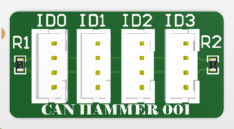
Maybe I’ll get some made at macrofab and pass them around for cheap.
Only caveat is that for this to work properly we may need to remove R401, that’s the same designator on both the standard 4.12 and the X. It can be done with a single iron, so you don’t need anything special. Not 100% on that yet.
2 Likes
Not so weird:) gnd is connected together already (battery input), else the pwm signal wouldn’t have anything to compare with and therefore not work.
Haha, love the name. And yeah, I’d be seeking expert opinion before pulling components off 4 VESCs.
I’m not sure how much it matters as we’re not looking at a 30m long can bus, but generally I think you’d aim to minimise the length of wire running from the bus wires to each of the nodes (VESCs). And bonus points if the bus wires are in a twisted pair config.
1 Like
@chaka what is your current feeling on this? I was looking through old threads and I see you favoured a splitter. This was a couple of years back so as we know a lot had changed since then!
Yeah that was a long time ago, I use the canbus these days so I can get telemetry on the whole system.
1 Like
So you’re running master/slave or is their a way to run them teamed with canbus?
Yes, master>slave, sadist>masochist, Master>Blaster…
3 Likes
is there any benefit to using signal + ground versus just signal on the parallel connection?
I don’t know if it’s necessary but I use signal and ground and it works
1 Like