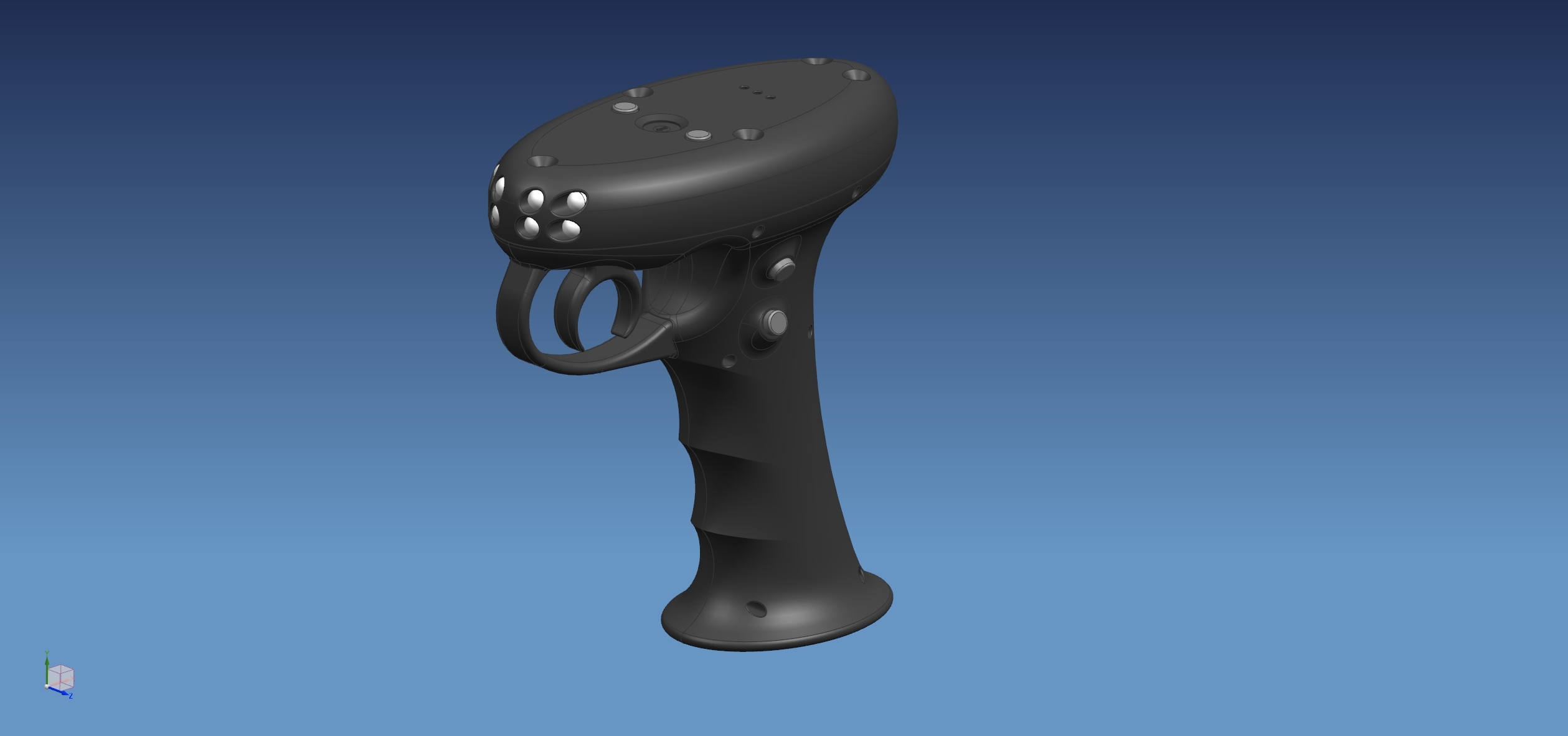
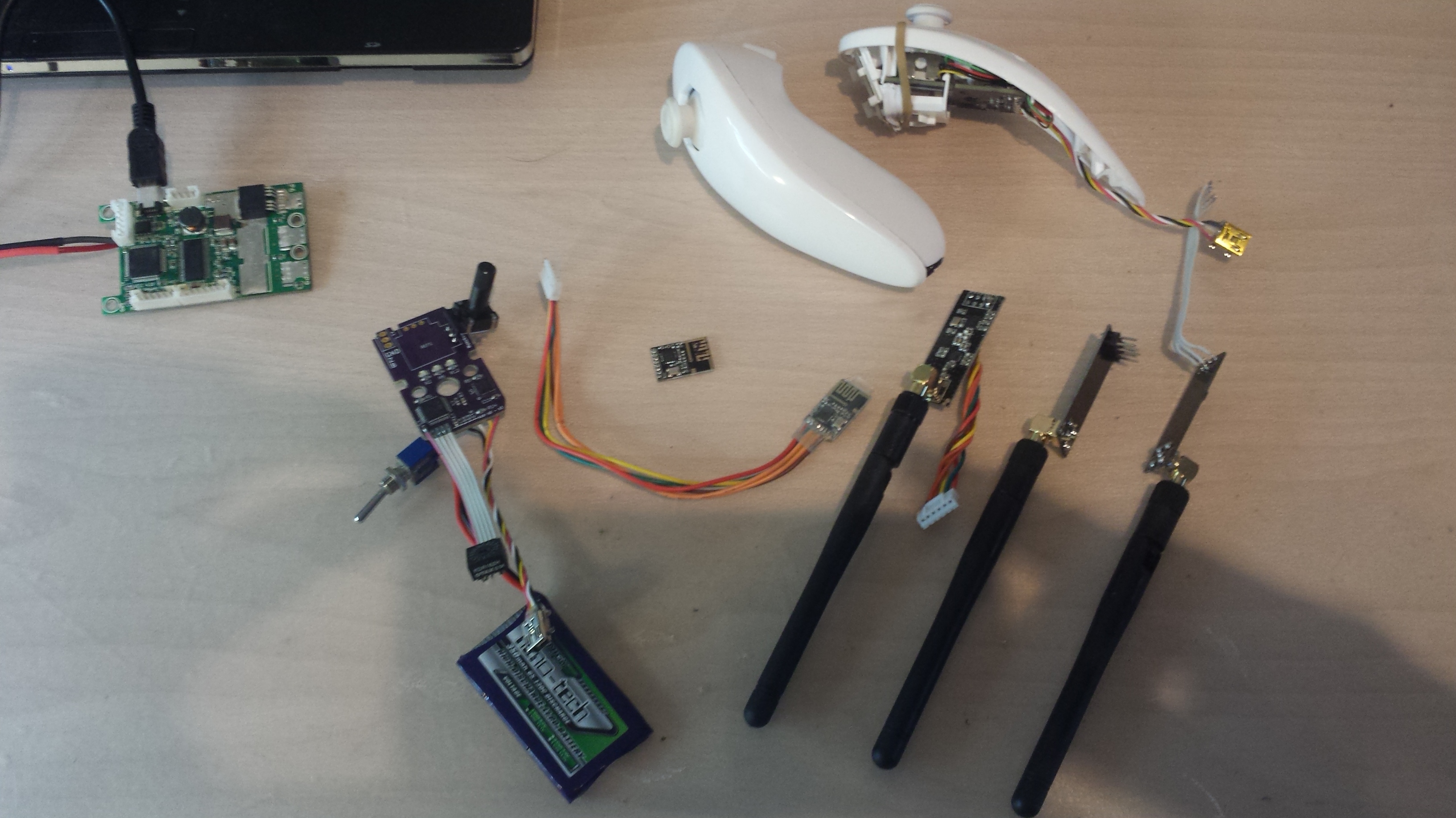
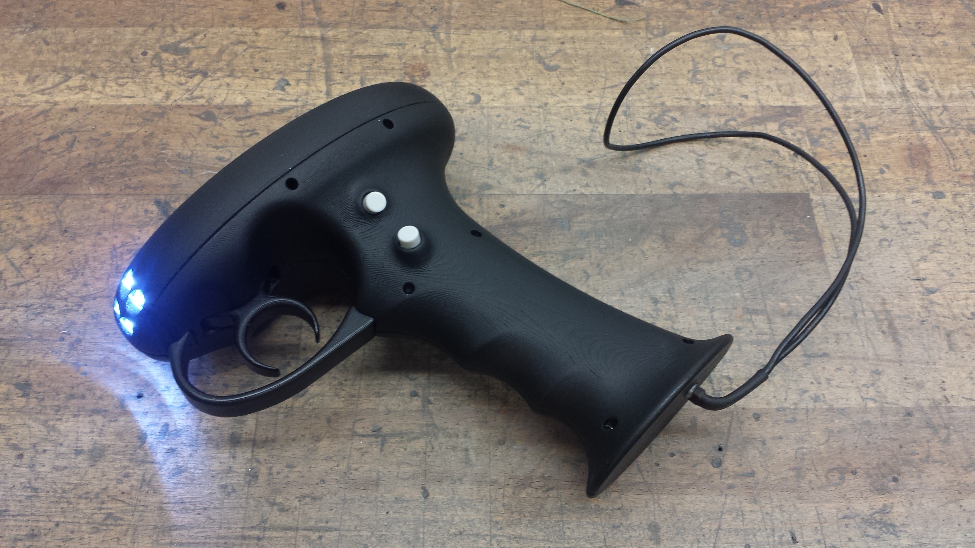
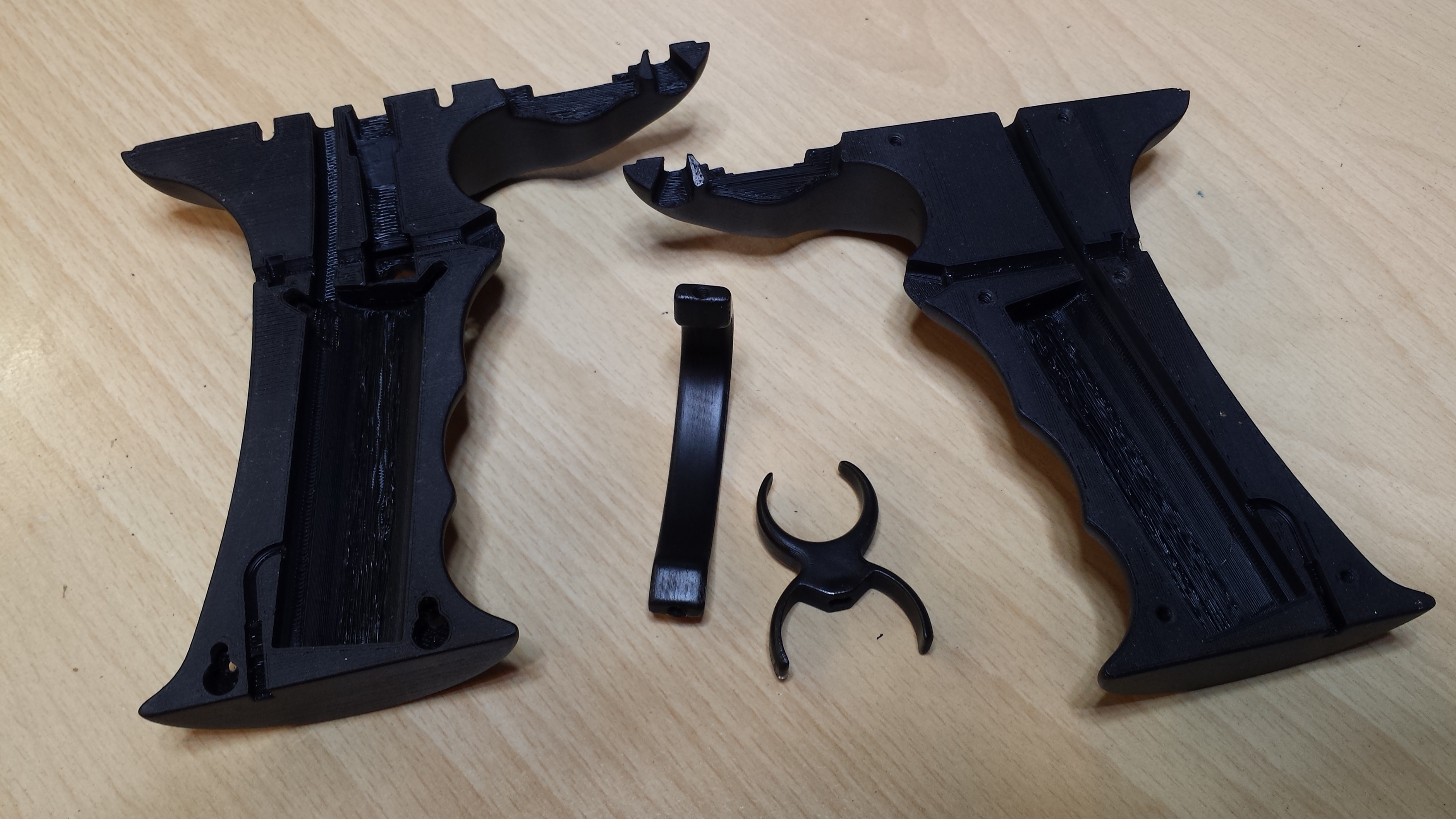
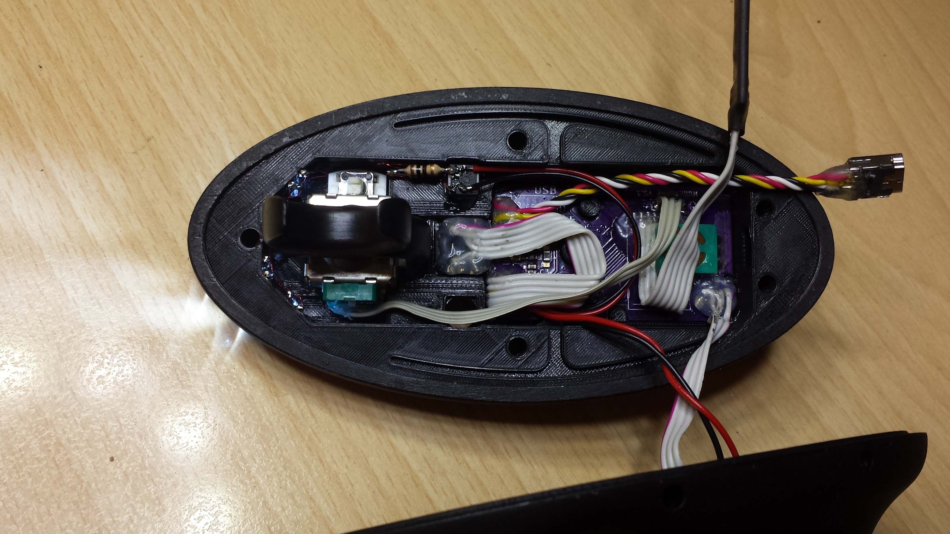
Hi there, I wanted to show you my VESC NRF Hand Controller. It is based on Benjamin Vedders Nunchuk RF PCB and can be used with any VESC. In fact it is a NRF Nunchuk, put into a 3D printed case to get rid of this little thump stick and to convert it into a trigger.
The battery and the C + Z buttons are located in the lower halves of the case. The connector at the bottom is for a safety leash which shuts down the electronics if you loose the hand controller. If configured right, the VESC goes into brake mode with configurable braking current when the connection drops.
The buttons on the top are for the LED light and an hardware beginner mode. Two resistors can be switched in the line of the thumb stick to limit acceleration and braking power to 50% and stretch this 50% to the full mechanical trigger move.
(Yes it is really this simple and works perfect…)
How did you make the surface of the 3d printed material so smooth? Did you just sand it down and then applied some coating? I know there are a few methods but it seems you can get mixed results based on what material and what paper/aceton etc you use…
So would be cool to find more details about the nice finish of the 3d printed material!
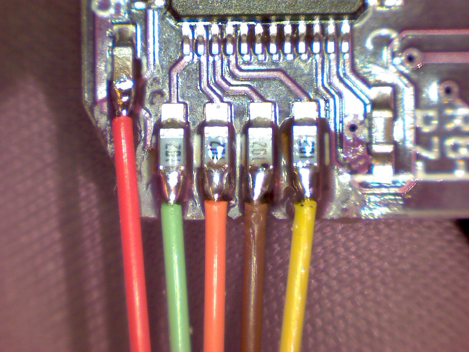
Is this the right resistor value you used - 4.7k Ohms 5% ?
I might say you are a genius lol who knew it could be so simple as just wiring a resistor(s) in the line with wires…
Also - in which 2 wires the resistors should be wired in ? Im not that familiar with resistor basics anymore, so a little hint would be helpful…
** Extra question **
Do you think the same value resistors will work for any potentiometer? Could you give some details what value pot you had, so others could compare, if they have the same?
It looks like you also made a ‘‘dead man’’ switchWhich type of connector you used for that?
It looks something similar to these JST connectors but im not sure
This is probably the least significant question from all but non the less, would be glad to know which one worked good for you, as I assume the connector has to snap out easly, to really work as a ‘‘dead man’s switch’’
nice one ! still a bit “big” too me as I prefer stealthy remote. I had Vedder NRF in the nunchuck in testing two years ago on my Busted board build; It was great, but I has some really weird behaviors time to time. It seems the NRF has some issues but then I moved to GT2B as I cannot afford to get this issues in Paris downtown.
I already made some test prints, results are not good as yours but I will try to adjust better printing parameters. What kind of buttons did you use on the top and on the sides of the controller and can you you give some details on the antenna mod of the NRF? I know you already told me in Hasloch but unfortunately I can’t remember
As I used PLA, I couldn’t use acetone vapor to smooth the part. It is just roughly sanded, afterwards a bit ground with steel wool and afterwards spray painted with matte paint. I use to spray the last layer(s) from a too far distance to get some extra matte speckles which cover printing and sanding artifacts better.
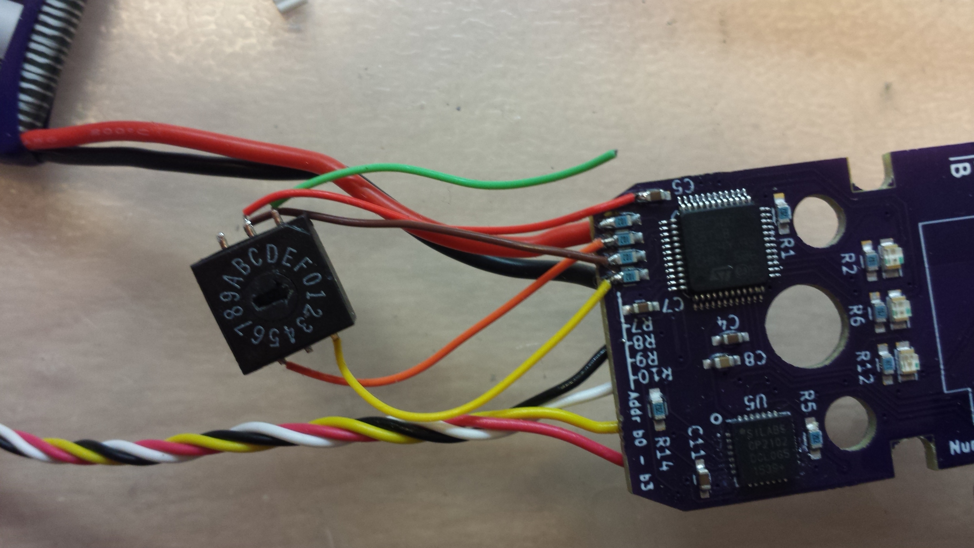
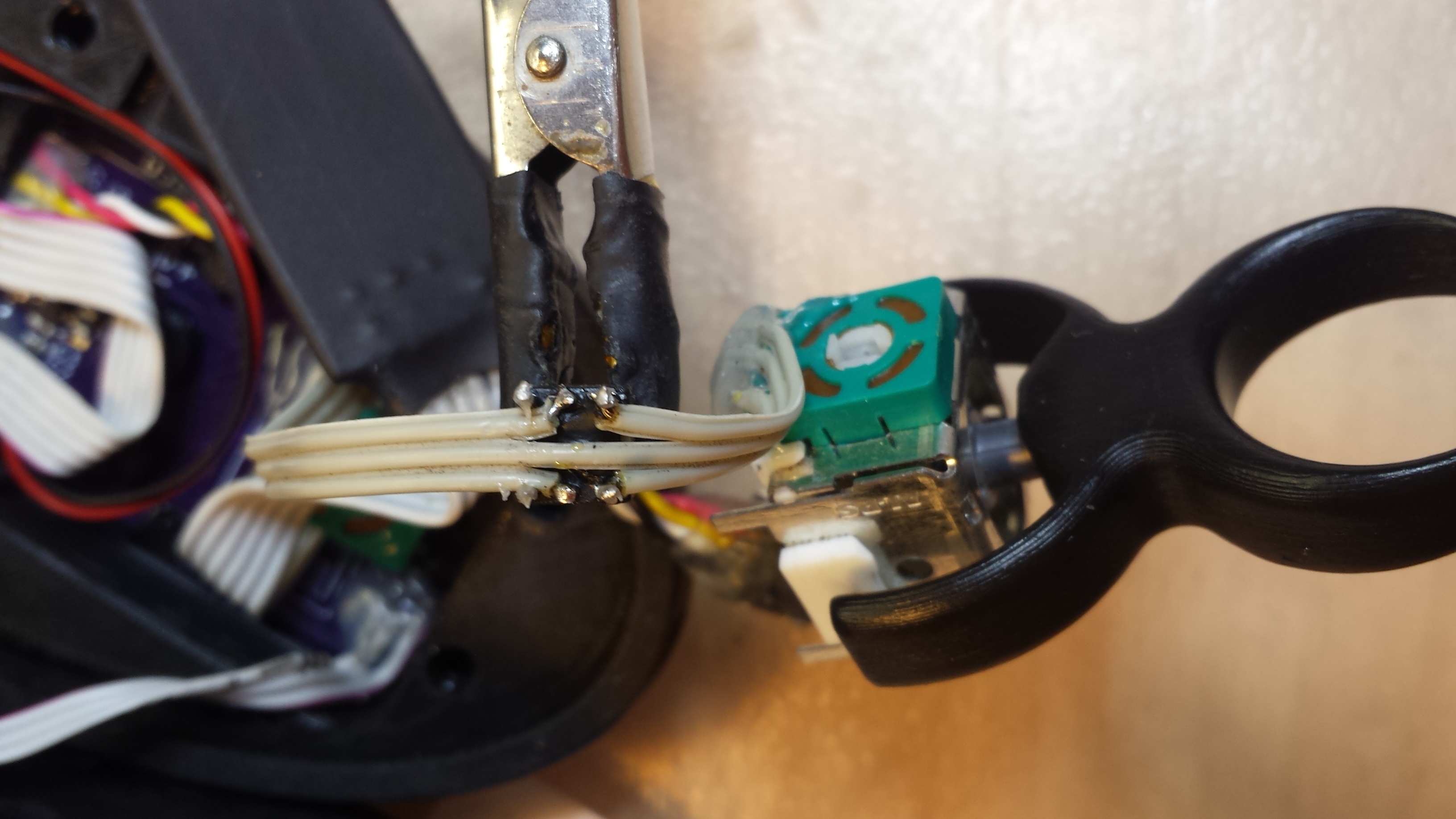
Yes you are right, 4,7kOhm. But it does not have to be exactly this value, you could even use variable resistors and trim them to the value that gives you the percentage you like. The potentiometer in the thumb stick has 10kOhm. So in line with 5+5kOhm you shrink the trigger range to 50%. They are connected in the ‘outer’ both wires of the pot and get shorted to 0Ohm (each) by the switch to get 100% power again.
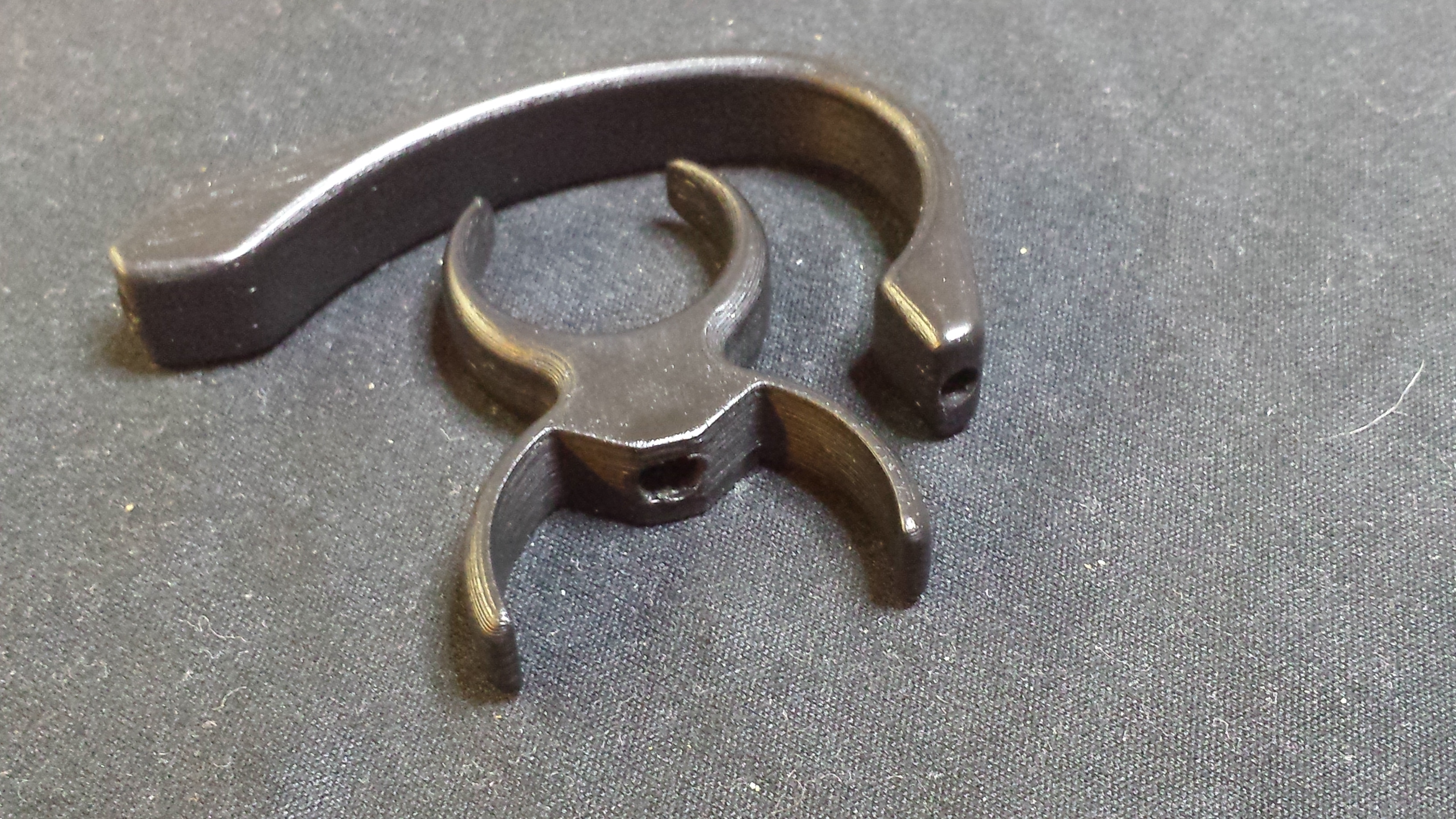
The connectors are called ‘Losi Connectors’ / Micro-T/B/DT. They do NOT snap out easily as I want the remote to shut down only when I go down so hard that I loose it. The second purpose of this is to simply switch off the remote, whitch does not work properly with any switch I had, because the charging electronics on the PCB is very sensitive to any resistance in the connection to the battery.
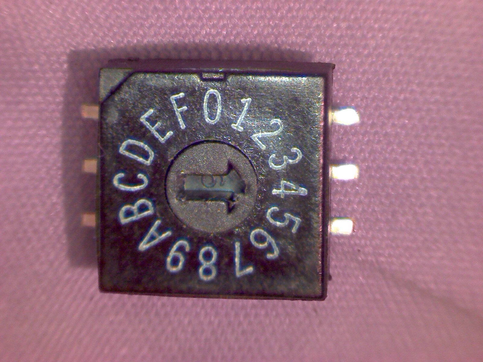
Btw: You need to disconnect and connect power when you change the NRF ID, because it is only read at startup… This got me some grey hairs…
@wmj259:
I’ve no idea what type or brand these 18650s are. I put new cells in my cordless drill and used the old weak ones for this NRF remote.
@unik:
I’m riding nunchuks since the beginning and I’m so addicted to the reverse and cruise control buttons that I can’t imagine something else. With the original Kama nunchuks I had always connection problems and dropouts at higher currents. With the original SMD NRF remote this got much better but was still not perfect. Finally the bigger long range with antenna work perfect and reliable up to 50m.
Very important is to lower the ‘Timeout when no control signal is received’ from 1s to 100ms. Else it is possible, that the VESC keeps the last received command for 1s when the signal drops out, which happens mostly when you command full throttle… Don’t ask how I know… Ouch…
The next important value is ‘Timeout Fault stop time’, which should be lowered from 1s to 100ms. Else the VESC needs 1s to recover after a short cutout which leads you to give even more throttle and tends to knock you off the board if the VESC powers up again.
The antenna mod was really simple: I pulled the antenna apart, desoldered the brass tube from the shielding and replaced it with a piece of wire of similar length. Additionally I cut the SMA connector and soldered the coax wire directly to the NRF PCB.
@Duffman Thanks for your response! I assume that spray paint finish on top of the smooth surface really makes the plastic stand out from the ‘‘unrefined 3d prints’’
Other than that - will have to probably play with pots some day and see how the values change, so thanks for going in detail with this one and mounting a little pot instead of resistor might be a good idea, at least till the ‘‘perfect’’ value is met
Well, this is something interesting I have not heard of… is it original nunchucks pcb which is sensitive or you meant your own etched pcb? (It looks like you made your own , sorry I I skipped something)
From your posts it looks like it is possible to overcome the nunchuks ‘‘finickies’’ / difficulties, if you plan ahead… otherwise a feature rich remote, if you get it working properly… which it seems you did in the end
The PCBs were manufactured by OshPark and self assembled.
The charging circuit in combination with the voltage regulator on Benjamin Vedders Nunchuk RF PCB are sensitive to the resistance in the battery cable. If it is soldered directly or connected with a low resistance connector it works without problems, but when you put a switch in the power line, the submitted throttle value swings by some ten percent around the actual value.
@Duffman Ok, so from you I understand you get an ‘‘interference’’ for the throttle value… just from the switch alone…
that’'s something I have not heard of but I assume sensitive electronics does get interference more easly…
Might as well measure resistance of my dc switch Im using for the board… who knows, perhaps it is eating up a few watts without me knowing
–
Anyways, at least now I know the reason why you had to go the ‘‘connector as a switch’’ route… that was one of the first things I saw interesting that you had developed such a refined circuitry (wiring), just to accomodate the physical connector…
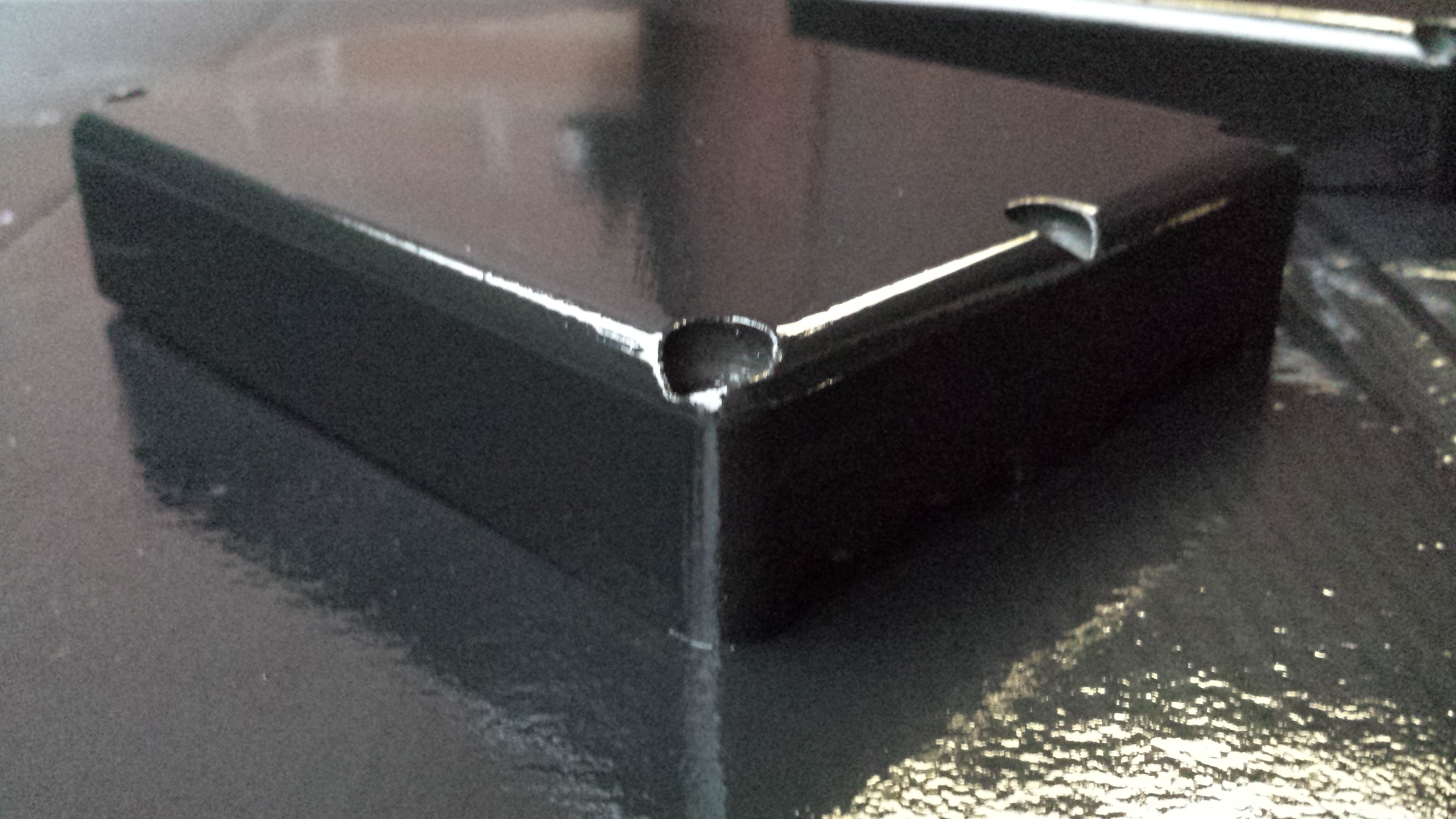
A bit off topic, but this is how I post process my 3D printed parts. The shown are not realted to this remote and were actually printed on a professional 30k€ printer, which also suffers a bit from Z wobble and blobs.
First I roughly sanded the print to get rid of the printing artifacts:
So here is the trick: For the last layer I sprayed from a too far distance to get little blobs and speckles on the surface, which hide little imperfections:
I am actually a little disappointed with the print quality when this was in fact a 30k€ printer.
A uPrint SE gives you basically the same level of quality (you can look at my prints) and costs like a third of that.
But nice trick to get the surface smooth. Did you ever try acetone vapor?