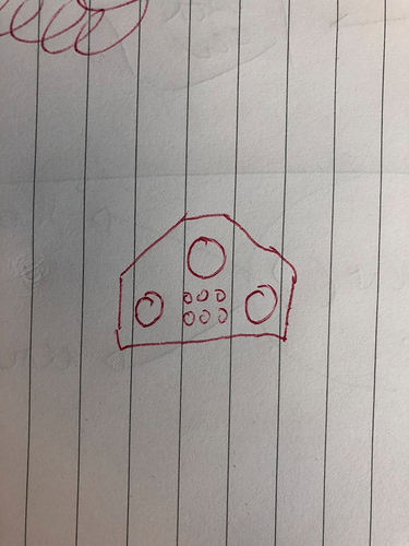
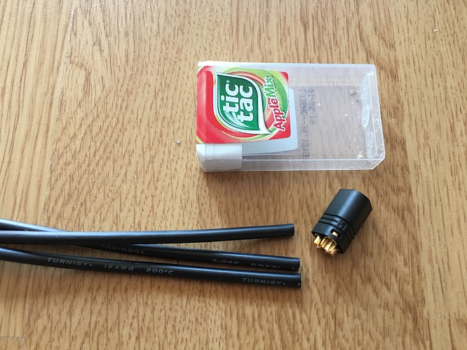
I would love this style is they had 3 xt90 style power poles and 6 these small ones for sensor wire. I can guarantee there would be like 100 people who already would buy it 
The center ones look like 0.8mm and big ones are 4.5mm
If these 100 people would buy 10 pieces each then we can talk to the manufacture ![]()
I like the idea for the new enclosure, looks good! How much flex and curvature has your board?
If they could make something like this:
In black then we could start arranging group buy or etc because this would solve almost everybody problems…
Best way would be printing it vertically but that requires a big printer.
But i like the idea, especially interested in how it works out with the foam.
It’s the MBS Core 94 deck. It says “stiff” in the specs. As for the curvature, if the box is 28 cm wide and centered on the board, the sides will be 5mm above the deck .
Right. I guess that would work. It would have to be secured somehow else it would flip over. I have never 3D printed anything, so I don’t know how these things are done.
Inspired by @rich, I got some of this stuff. I think it could work pretty well for padding.
They just arrived. I guess I understand what you were talking about now. Bloody hell, these things are tiny!
OK, challenge accepted. I think that will be a long night. ![]()
That could be adjusted in the 3D Printer Software (Slicer), no problem i think.
Please only use them if you really think that there’s no possibility of shorting out, touching phase wires can really fuck up your ESC and it would be a pain if it’s just because of hobbykings shitty connectors. ![]()
Yeah, I was thinking the same thing. Using these is really asking for a short circuit. I’m going to keep as much insulation on the wires as possible and maybe add some heat shrink as well if I can squeeze it in.
The connector has two parts. The other part is plastic only and it has little plastic separators inside, which should keep the wires away from each other, so it’s not that bad.
No worries about shorting, slide heatshrink on wire, solder wire, slide heatshrink down over connection.
I tested it and it doesn’t work if I want to use that plastic part that keeps the wires separate. It’s a too tight fit. I haven’t been able to squeeze the heatshrink in. I guess I don’t need to use that plastic part though and use heatshrink instead.
Bugger
characters
Agreed it sucks and is messy if not really careful but you can trim down the exposed wires a little to fit when tinning you ensure they are all neatly melded together…extra work for sure
Yeah you are right, I also soldered trimmed down 10AWG to 3.5mm bullets but it’s not something I like. Flux helps a lot on thicker wires.
Wire strippers to make the trimmed end uniform
It’s done!  Wasn’t that hard after all, even with 12 AWG.
I didn’t use any heatshrink at last. Only the plastic cover. It’s pretty hard to take off, so I guess it’s less likely to slide off the wire than heatshrink.
I have done some measuring with this jewel and looks like I managed to do the soldering without creating any shorts (which really surprises me  ).
).
Did you heatshrink the connections in the end?
Hope that voltmeter still works, but nonetheless a nice piece of vintage tech 
No, I didn’t. It was either heatshrink or the plastic cover. The plastic cover wouldn’t fit over heatshrink.
Of course it works! Good old Russian engineering. It’s practically indestructible. ![]()
To be honest, I find it a bit of a miracle that it still works. It must be like 50 years old. Only recently I discovered it has a battery. Of course it must have a battery! How would it measure resistance without a battery. Silly me. Anyway, the battery was of course long dead and leaked. The multimeter still worked though. It doesn’t need a battery for measuring voltage. Then I replaced the battery and it can even still measure resistance. Indestructible! ![]()
Did the solder flow all across the wire? from the picture it looks like it didn’t heat enough to make a secure connection, the wire must be all soaked in it to make a strong connection
It didn’t flow across the wire, but I believe there was enough between the wire and the metal and it was hot enough. It might have been better to use a bit more of solder. I was worried about using too much. First, things are really tight there, so excess of solder would likely get in the way when putting on the cover. Second, I was afraid that if the solder overflows, it might create a short since the connectors are really close to each other. I’m pretty new to soldering.
The wires hold on really well. The question is if I can get enough amps through. Is there an easy way to measure that?


