Won’t watts be worse? Temperature is mainly dependent on current and not voltage AFAIK. Like you can push say max. 40a at 6S or 12S without overheating but the watts will be vastly different.
1 Like
@Maxid … not as far as I understand. It seems to be the case with some things where only amps matter (eg: wires) … I don’t understand why but say 10 AWG is rated based on amps, but can do up to 600v. The amps matter, the volts don’t so much. Do not understand, but this is the case.
With current running through the controller, it matters. See Vedder’s video where he is demonstrating that the 4.12 VESC can run at ‘34amps all day’ … he was at 21v (from memory), but for sure and certain at 48v, this is not true. We know this, because we tested it in a lab. It can probably run at 600w all day, but not 34a at any input voltage.
There are plenty of people on this forum smarter than me who can explain this. It got a bit of airtime in the other thread I pointed to … you can’t have any amount of volts and I’m certain based on our testing that you’d be creating vastly different load with 40a @ 6s Vs 12s. You might not overload them at 12s, but it doesn’t mean the load is the same.
You’d could ride it uphill for a long period and monitor it on an app to see . Uphill will draw a lot more current than top speed on flat ground. You’ll max the system out much faster as you’ll draw max amps this way. Obviously depends on your weight etc, but this is a general rule as far as I can understand.
Cheers
Hmm, that’s interesting. People say that temperature is related to current and not watts because formula for heat produced in a resistor is I^2R( I am sure almost everyone here has seen this). But that resistance R might not be a constant like we assumed. Maybe it does change with voltage, then we’ll see the effect you are talking about.
The 4.xx VESCs are famous for going poof above 10S. Wouldnt recommend going past it. Not sure how far down I have to go to make you understand the concept of Voltage and current. But yes. Voltage only describes the potential between to conductors. to carry large currents you need fat cables or pcb traces, no matter of voltage.
Watts are simply a measurement of energy and not only coorelated to electricity.
Correct, By increasing the Voltage, the amps needed to be drawn to produce the energy needed to propell you forwards are less. And the other way around obv.
Resistance Changes with temperature. google superconductors and you’ll understand.
Just from today:
at this point is an unproven conjecture and is no more correct than @amf
Until there are side-by-side tests, it’s just one person’s opinion versus the other.
I am pretty sure @Blasto has done those tests. Up until today I thought we all agreed on P=RI² being the one formula to consider for our electronic systems. I am open to be proven wrong though. @all: who will do those tests and publish them?

1 Like
using a pseudo random fet, all same circuit, with a 50A load. input voltage varying between 20V to 50V with a 10V increment
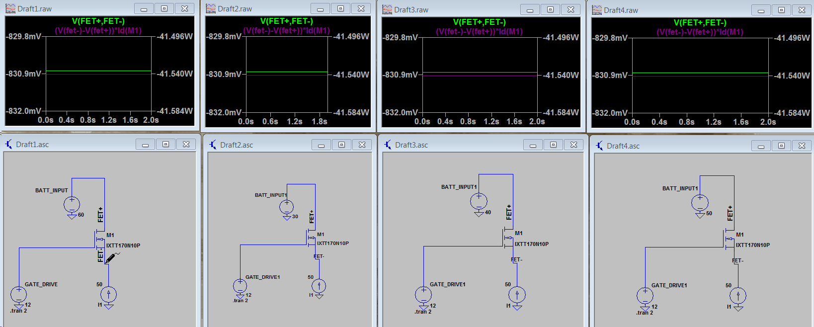
All the same drop across the fets
1 Like
LTspice ftw, what conclution are you trying to reach with the sim? Only the losses?
that input voltage is irrelevant for max current and thermal testing
Alright, the delta voltage is a function of the resistance thru the FET, which once again brings up the P=UI, U=RI → P=R*I^2.
Showing the square relation from the current. Anyone familiar with a exponential function knows that the current is the heaviest factor. Are people still debating this? ![]()
![]()
@linsus Can I ask you a more technical question? Since rpm depends upon voltage, and since higher switching frequency leads to higher impedance in the traces+mosfets, is it correct to assume that driving a motor with higher voltage at the input could produce more heat in the esc(because of the higher impedance)?
1 Like
Its a complicated question, switching frequency depends on sevral different factors other then the voltage level. But yes the RPM or ERPM is directly correlated to the switching and while i dont meddle with power electronics that much as a proffession, I know quite abit about semiconductors. I’m afraid its not as easy as a yes or no answer. Both current and voltage play a part towards the actual losses while current being the desiding culprit. One cant exist without the other.
1 Like
I agree, fairly certain at this point that current dominates the losses overall for the eskate operating regime. Started looking into modeling the FETs in the system analytically and it was way more complicated than I anticipated and got lazy a few hours in.
As far as real world testing, ran some tests on the unity comparing our bench testing of 60 amps through motor at like 5-10% duty cycle vs. real-world hill climbing of 60 amps at around 80% duty cycle. In terms of thermals there wasn’t much noticeable difference in the rate the boards heated up suggesting that motor current and not power is the best indicator of heat losses in the FETs.
1 Like
@Blasto But this is kind-of irrelevant because the average current in the ESC is probably limited by pulsewidths and impedances, and not by voltage drops across resistive loads.
We just need a side-by-side thermal test with same load on identical esk8 ESCs (using mechanical resistance on the motor axle) but different battery voltages.
Amp rating is for copper wire while voltage rating is telling you about arcing protection that cable insulation provides.
3 Likes
Thanks @Deodand … this thread of amps / volts / heat is running in several places. Seems like motor amps (which seems to be a 'balancing number) Vs battery amps (less efficiency loss). It would help if the real world was bench simulated so that there’s consistency in how this is talked about. There is a long rant here from 2016 which goes into a lot of detail http://buildelectricboards.com/showthread.php?tid=164&page=2 … about how the battery and motor amps balance out.
When we tested our worst case of max motor torque based on full input of 48v/30a constant, we get a reading of someone doing their worst until the battery runs out. We are trying to make sure nothing can be broken. It was explained to me that there is less going to the motor due to efficiency, but this nonetheless represents our system running at full torque @ max speed the torque is available.
I’m not sure that the ‘80 amps all day’ statement is a good description of what the controller does. Even the Maytech 100a … with no airflow, it won’t sustain our test for longer than 10 minutes before it gets to 100 degrees. So, this is not 100a … we are using 30a. Obviously, the 100a is the wrong measure and is maybe a peak inbound measure … or something.
Not sure of the solution, but we are doing our own testing as we can’t work out from the marketing material what the actual maximum thresholds are. It’s not the same with commercial controllers. What they will do is very clear.
The VESC community ‘big brains’ could devise a series of measures / tests that all vendors need to supply data for so that comparisons can be made … now that would be interesting 
Cheers
Maytech is responsive and more honest
Flipsky is just bullshit, no R&D, but just sell cheap price by changing low quality components.