The issue with these profiles is that they are showing you what the distance between teeth are on a flat section of the belt. Once the belt meshes with the tooth it is no longer straight and the center to center distance is actually the arc length of the segment of the pitch diameter between two teeth. I’m on my phone at the moment but once I get to my home computer later tonight I can upload the profile I use for a singular tooth then pattern to create any sized pulley
2 Likes
This 's almost exactly the same numbers that mine had. I dimensions mine different to allow for changing the number of teeth and keeping other relationships intact. @mishrasubhransu
I agree, this is not how I would draw, I just imported the profile and put the main dimensions so people can use then as base to draw any teeth count My plan is to get some pulleys made from wire EDM since I can only find aluminum pulleys around here and they are experiencing significantly wear, but no point using EDM with a profile that is not exact
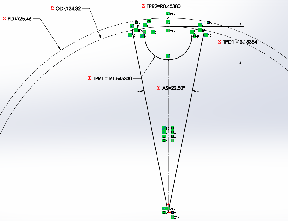
So you can use the 10 Degrees for 36T or you can do what I do which is create the tooth profile and dimension the width of one tooth to 4.898mm. The two lines coming out from the center of the 25.83 circle and meeting the radius are normal to the radius and I set a geometric constraint there. You have to then set the rest of the geometric constraints to the profile, like the tangent intersects between the .458 radius and the 1.543 and the short segment connecting the .458 radius to the lines coming out of the center is actually a straight line, there’s no arc. Its so short it wont matter. You can then circular pattern the one tooth slice as many times as you want and then select the corners and coincide them and you can create a pulley with any number of teeth.

1 Like
Just use this:
@mishrasubhransu You can always download the profile from the vendor website in any 3D version you want like from http://shop.sdp-si.com/catalog/product/?id=A%206A25M040NF1510
Just click the download cad banner

This works great for commonly available sizes bur for example, 42T HTD5 does not exist commonly, you will have a hard time trying to find that online. Its quicker to create that yourself. Also, you can create odd numbered pulleys as well which also do not exist.
to calculate the pitch diameter you can just multiply pitch of the belt with the tooth count of the pulley and divide it by pi. for 40t HTD 5m this wil be (40*5)/3.14… =63.66mm diameter
Thanks everyone. The cambam profile didn’t seem accurate enough. I got the actual part from the manufacturer website which @Kaly mentioned and made my profile sketch like @JuniorPotato93 suggested. Made it match the original part as close as possible. Once the profile is done then it’s just a matter of using it for different number of teeth.
Here’s that information for future reference.

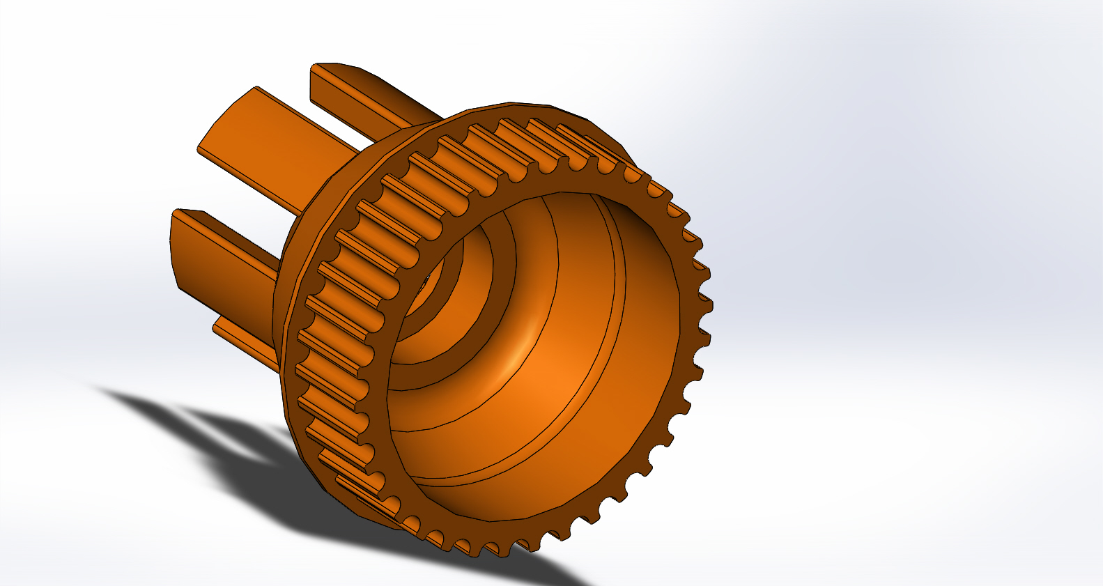
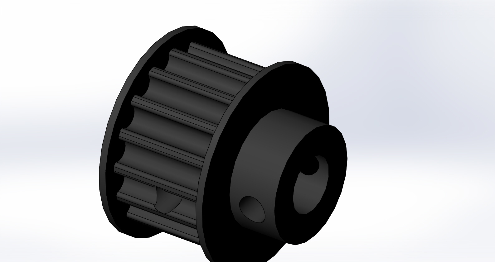
EDIT1: And this is what the pulleys look(40T, 36T, 16T)

7 Likes
looks like you hit the nail on the head with that. Hope it prints out well!
@mishrasubhransu How do you calculate the OD and U values? You calculate the U value from subtracting PD and OD, but then you use that U value to calculate OD?
@JuniorPotato93 Hi I don’t really understand your instructions about creating a pulley, I’m trying to make a really bit 188 T pulley and I printed one but it just doesn’t seem to fit. Maybe I am misunderstading your instructions?. I don’t get why the 25.83mm is higher than the 27.464 in your diagram
here you have the full explanation http://www.gatesmectrol.com/mectrol/downloads/download_common.cfm?file=Belt_Theory06sm.pdf&folder=brochure
1 Like
Looks really good. I replicated your equations in SW, but I am missing the equations for TPR1, TPR2 and TPD1. Are they constant regardless of number of teeth? And what about different pitch? I would be very happy if your share this information.
Thats a good question. Let me check.
I checked. They are fixed values in my equation. Maybe that’s what I got from the cad from the websites.
Thank you very much for your effort.
It is a little odd, because your values are just a little different from the ones downloaded from sdp-si.com.
The reason I ask is that I downloaded and printed some wheels from a German website and they performed terribly, but they had quite different geometry from what I later purchased. So now I want to know, what is “correct” if anything is.
I don’t exactly remember which website I followed, but the designs have served me well. Haven’t had a belt broken in 2 years, riding roughly 2 miles daily. This is a new pulley that I printed and this is how the belt fits.

4 Likes
Great, thank you. I will go on with your values 
printing gears is also a bit trial and error imo, nozzle diameter and slice settings can change the gear tooth profile so it’s not exactly the same like in your cad software.