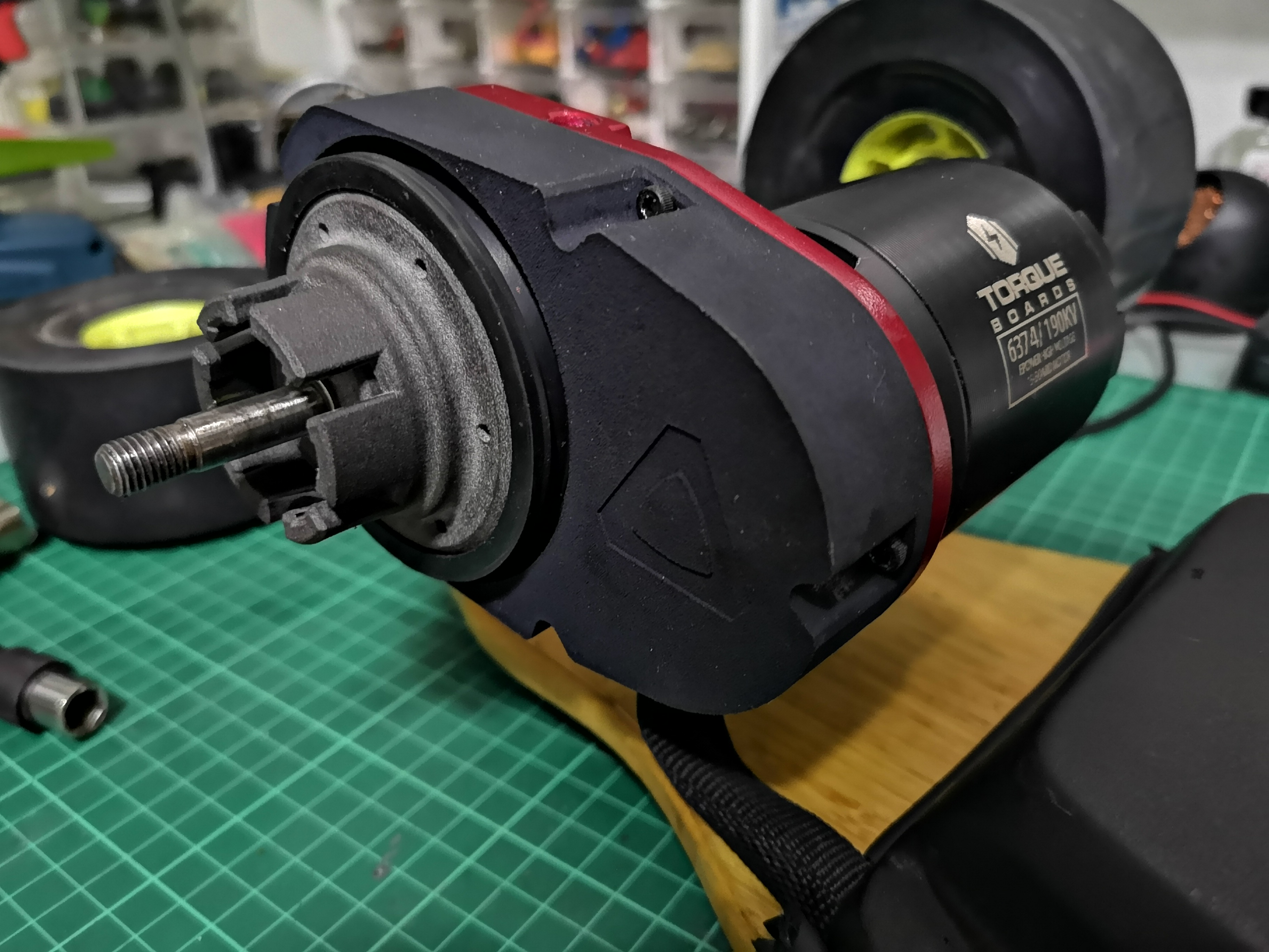
Introducing the Aortal Gear Drive:
https://goo.gl/forms/xms9KmjyYpWPvJ2j1


Price:
$150.00 USD incl. Intl Shipping (TENTATIVE PRICE, expected to increase)
Specs:
- 2.65 Gear Ratio (45:17)
- Ability to accommodate 63xx Motors and 97mm wheels or larger.
- Compatibility with Caliber ll styled trucks (A standard Caliber truck can fit a single drive with any 63xx motor while an E-Caliber truck or a TB218 truck can fit dual drives with 6355 (possibly 6374) motors)
- CNC-ed T6061 Aluminium Motor Mount
- CNC-ed POM [45T, Mod1.5, 15mm] Spur gears
- EN34 Case Hardened Steel [17T, Mod 1.5, 15mm] Pinions (8mm Bore)
- HP Jet Fusioned Nylon Gear Enclosure, Hangar Adapter & Wheel Adapter
- NBR Rubber V-Ring used as the sealing method
- PLA Bash-guard
Instructions:
Tools you will need:
- Torque Wrench capable of 16Nm or greater with a size 4.0 Male Hex Bit
- Size 4.0 Hex tool
- Size 2.5 Hex tool
- Loctite 638/648/680 or similar
- Loctite 242/243 or similar
- Gear Lubricant (Grease)
PICTURE OF TOOLS TO BE INCLUDED
The Aortal Gear Drive Kit includes:
- 1x Aluminium Motor Mount
- 1x Nylon Gear Enclosure
- 1x Nylon Hangar Adapter
- 1x Nylon Wheel Adapter
- 1x POM 45T Spur Gear
- 1x Steel 17T Pinion
- 1x NBR VA-60 V-Ring
- 2x 6706RS Bearings
- 4x M8x30 Set Screws
- 11x M3x10 Socket Head Screws If Bash-guard package is included:
- 2x M3x10 Socket Head Screws
- 1x PLA Bash-guard
PICTURE OF KIT TO BE INCLUDED
(Installing the Motor Mount):
- Take the hangar out of the truck baseplate.
- Slide the motor mount onto the hangar.
- Slide the hangar adapter onto the hangar.
- Slide a wheel (with bearings) onto the axle and tighten it. The hangar adapter should be firmly locked in place.
- Turn the hangar wheel side down and the motor mount should sit flush with the bearing adapter.
- Screw in 2 m8 set screws to the inner holes (the curved side) of the motor mount. Ensuring that the motor mount is flat, hand tighten the 2 m8 set screws.
- Check once more that the motor mount is flush with the hangar adapter. (This is crucial!)
- Incrementally tighten the 2 set m8 set screws to 16Nm each.
- Check again if the motor mount is flush (Have I not emphasized how important this is?)
- Screw in the remaining 2 m8 set screws into the motor mount holes and incrementally tighten them to 16Nm.
- Check to see if it’s flush once last time. I promise this is the last time! If it’s not flush, you’ll have to start over from step 6. If it is flush, in no particular order, remove each m8 screw, apply loctite 242/243 or similar, and screw and tighten it back in to 16Nm. You should only add or remove 1 m8 set screw at any one time.
(Installing the Motor & Pinion):
- Remote the wheel from the axle.
- Place the motor (NOT INCLUDED IN THE KIT) with the cable facing the board side onto the motor mount.
- Hand tighten the motor onto mount. (You should not be able to move it along the mount after.)
- Apply loctite 638/648/680 onto the motor shaft and slide the pinion onto the motor shaft.
- Use the 3d-printed washer provided to ensure the a 1.5mm gap between the motor mount and the pinion.
- Let it sure for a minimum of 30minutes before continuing with the installation process.
(Installing the Spur Gear):
- Lightly loosen the motor from the motor mount so you can slide it along the motor mount but not so much till the point where you can rattle the motor.
- Push the motor away from the truck.
- Place both 6706RS bearings into the spur gear.
- Push the spur gear to the end of the bearing adapter.
(Adjusting the Backlash):
- Using a piece of 70 to 80gsm paper (standard notebook paper), fold it in 2 and place it inbetween the spur gear and the pinion.
- Slide the pinion along the motor mount such that it forms a tight mesh with the spur gear and hand tighten the 2 motor screws furthest from the spur gear.
- Rotate the pinion or the spur until the piece of paper rolls out.
- Remove the spur gear from the bearing adapter.
- Tighten the remaining 2 motor screws.
- Similar to step 11, tighten all 4 motor screws to 6Nm each, with loctite 242/243 or similar.
(Installing the Wheel Adapter):
- Screw in 6 M3X10MM screws into the flywheel adapter.
- Place the flywheel adapter into the core of a wheel. (Ensure you,'re putting it on the correct side of the wheel, it should be the side closest to the bushings when you slide the wheel in.)
- Wrap the V-ring around the adapter and ensure it’s flush with the wheel.
- Carefully place the spur gear back onto the hangar adapter (the side with the larger holes must be facing you, away from the motor mount), ensuring it meshes nicely with the pinion. (Give it a quick turn to make sure it spins well).
- Apply your lubricant of choice to the spur gear and pinion at this stage, making sure both the pinion and the spur gear are coated thoroughly.
- Using 5 m3x10mm screws, secure the gear enclosure onto the motor mount.
- Remove the wheel adapter from the wheel while ensuring that you do not to move the position of the v-ring.
- Attach the flywheel adapter onto the spur gear by aligning the 6 holes of the spur gear with the 6 m3 socket heads.
- Install your wheels on the axle just like you would any regular wheel, aligning the spokes on the wheel adapter to the holes of your wheel core and tighten it. (Don’t forget your speed rings!)
- If you purchased a bashguard, install it with the m3 screws provided into the following holes.
- Voila! You’re done!

How many will you be willing to purchase?
- One
- Two
- More than Wwo
0 voters

I’ve tested my gear drive to the extent where I think it works well enough to be sold to the DIY community. I’d say that these are still in the prototyping phase and the price that it’s sold at reflects this.
More information on the testing process and updates on it are shared in post #55 and is tagged below as the solution to the thread.


