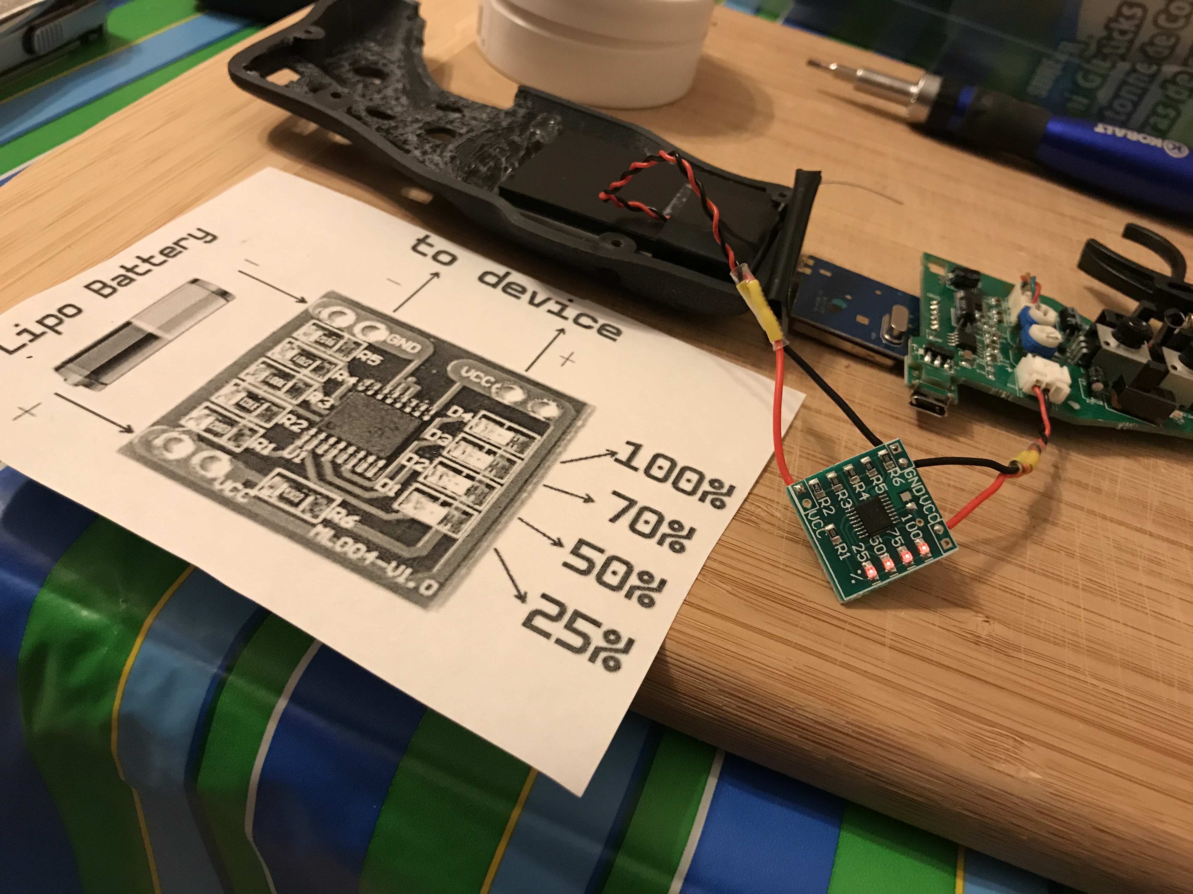
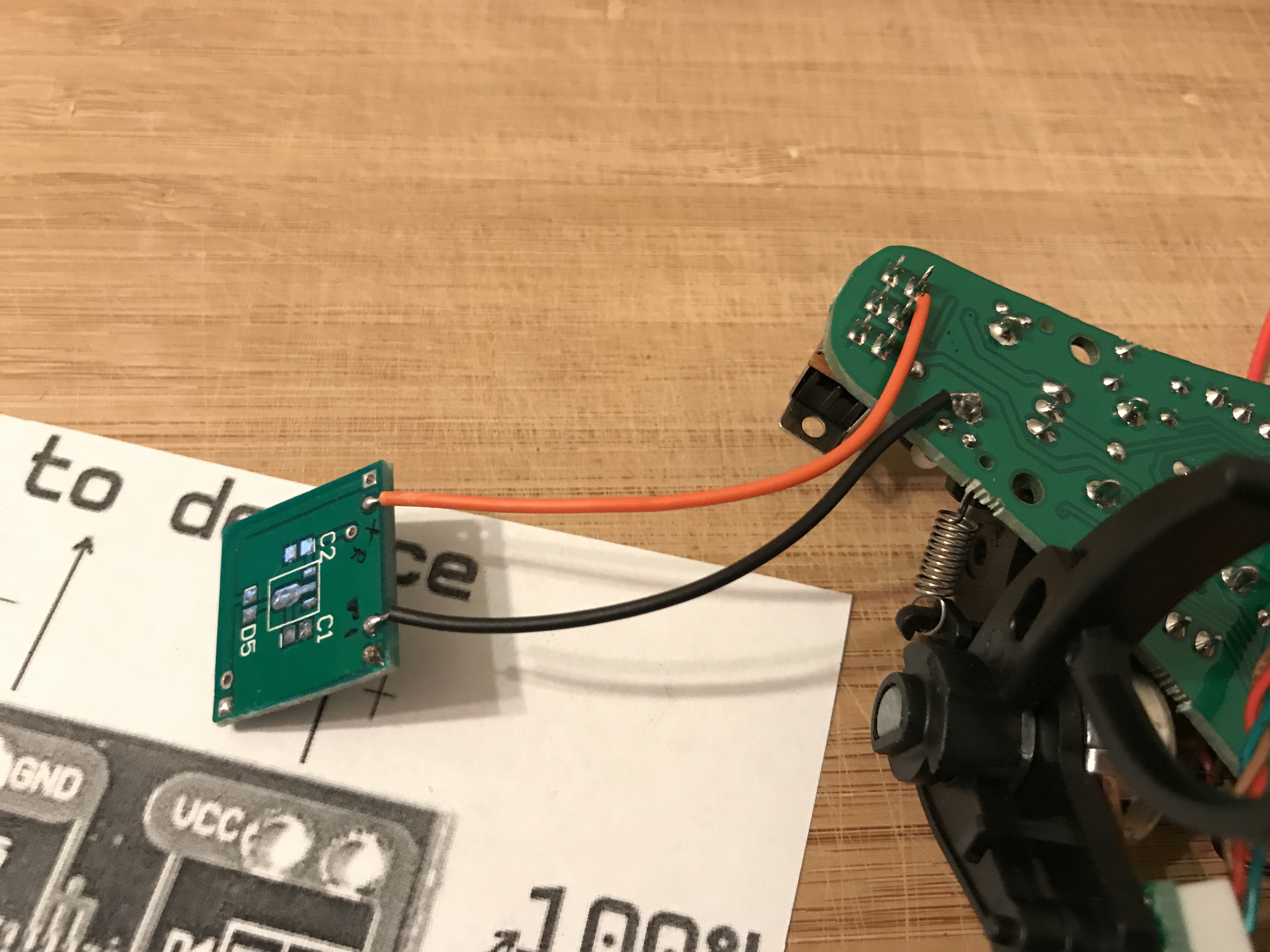
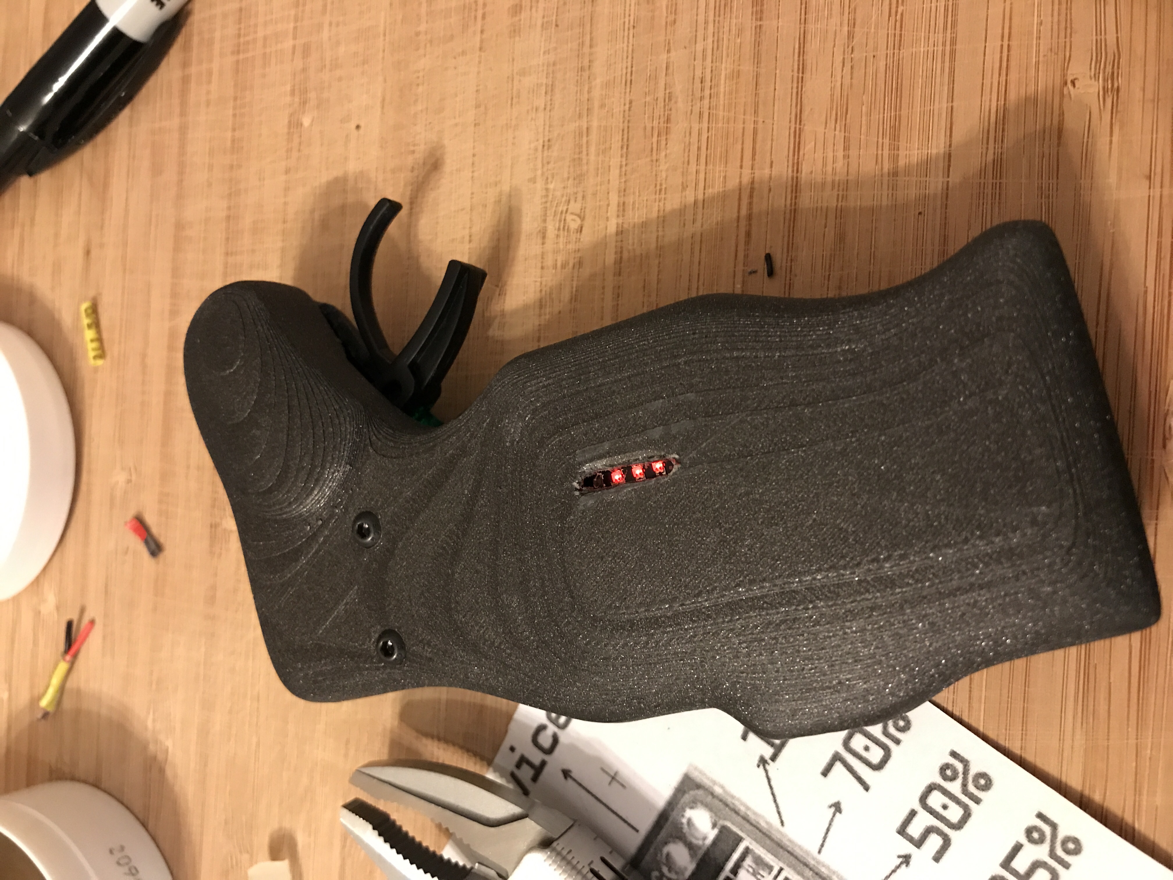
[SOLVED] ignore the picture on this post and ignore the diagram drawn on that printout. Solution is to leave the battery as is. You only need to solder two wires in total from the battery meter to controller PCB as seen on the last picture I posted a few posts below. Use a bit more wire than I did as you need room to move the meter to align with the hole you make, align it then use hot glue to keep it in place. Apply electrical tape between the two boards to prevent short, then put everything back together. This battery gauge was found on eBay for like $7 shipped
…
So I’m trying to add a battery indicator on my GT2B mod. Got the idea from @FLATLINEcustoms’ remote. After I solder what I think was correct the meter’s LEDs turned on but it’s always on. Does anyone know what I did wrong here?
I think you need to tap the battery power, after the power switch, not directly from the battery. Or the minus to the battery and positive after the power switch.
Looks like just two outputs and two gnd in case you need them can check for continuity on those holes without any power running into the board. Also like @lrdesigns said just need to put the switch on one of the battery leads between the battery and the meter so you cut off power to the meter itself along with the power it passes through.
Can see the traces from VCC just run around the edge of the board and gnd is hooked right to the battery gnd in the traces. Looks like the chip controls the gnd opening/closing for the LEDs to turn on based on the voltage it’s reading.
This is what I remember as well. Flatlinecustoms has his on all the time
If you look through that thread someone figured out how to make the power meter switch on/off with the controller. There was also something about replacing a resistor to make the LED brighter (which in turn draws more current, making the switch more necessary)
Interesting. I was thinking about adding another switch to turn the meter itself on and off. Which means I would have flick TWO BUTTONS to turn on the remote
You just need to solder on the LED positive wire to the 5V switched source on the back of the PCB, if I remember correctly. You could find it with a multimeter. Or go searching through that thread. Someone posted a picture of which solder point you need
They use such little power they stay on. Someone did the math and it was a long long long time to drain the battery. I wire mine straight to the battery. Very convenient to look at the remote and see how much power it has.
I don’t know. The winning most likely not. But I think the nano-x might have enough surface area. Just have to figure out if there’s enough space to add the thickness. This thing is a pain to take apart and put back together so I can’t check