SNAGGLEPUSS | *REBUILD TO ARBOR HIGHGROUND* | Dual 6354 | Dual Ollin VESCs | Mini Remote | Dual DIYv4 Mounts | DIY 13/36 | 8s3p 9Ah Zippys | 44d Caliber IIs | 97mm ABEC11 78a Flywheels | Kydex Box Enclosure

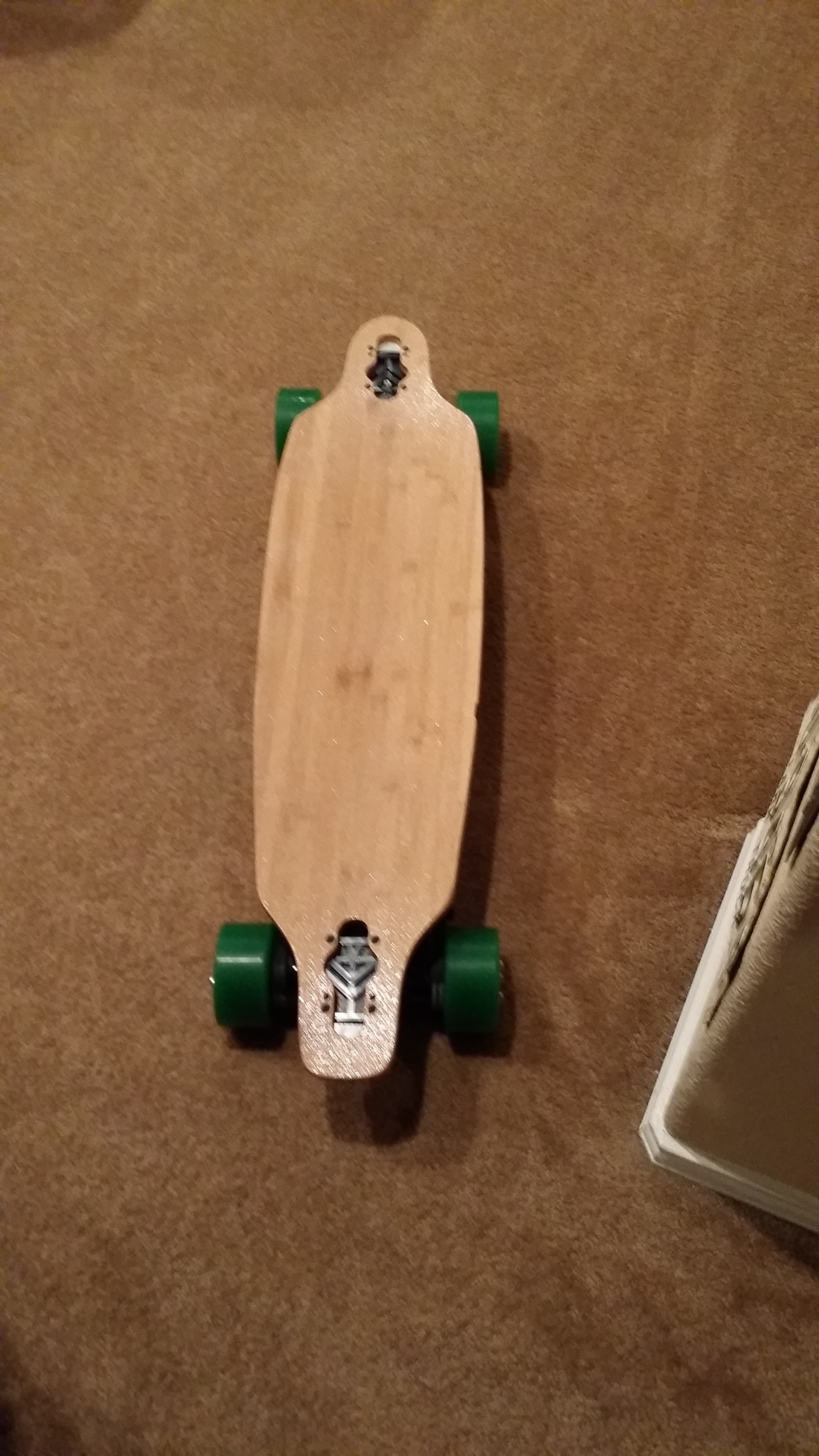
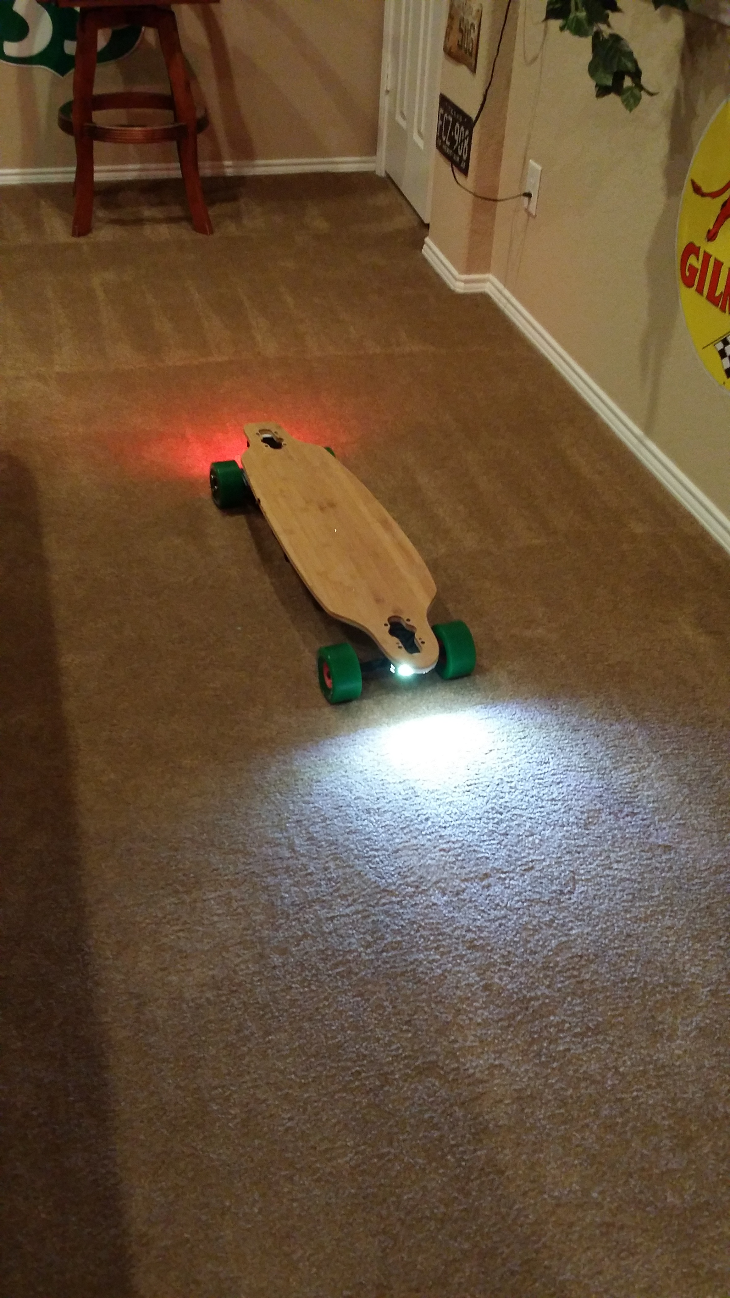
Bought and slightly changed @jwoodsentertainment 's deck and components he had for sale.

Changed to 8s because this is my first elec build. Used Balance Board from SuPower, bypassing current limit for charging.

SOLVED Can’t get Mini Remote i purchased from @JLabs to bind. (surely something stupid, but kicking myself here) SOLVED

SOLVED Added Battery Capacity meter (currently not working (I may have it wired in wrong)) {Nope, well technically yes, but the leads that came with the monitor were in backwards.}

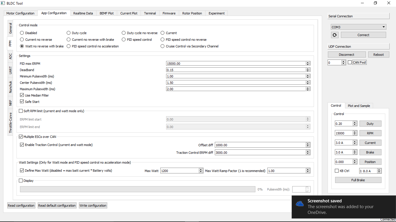
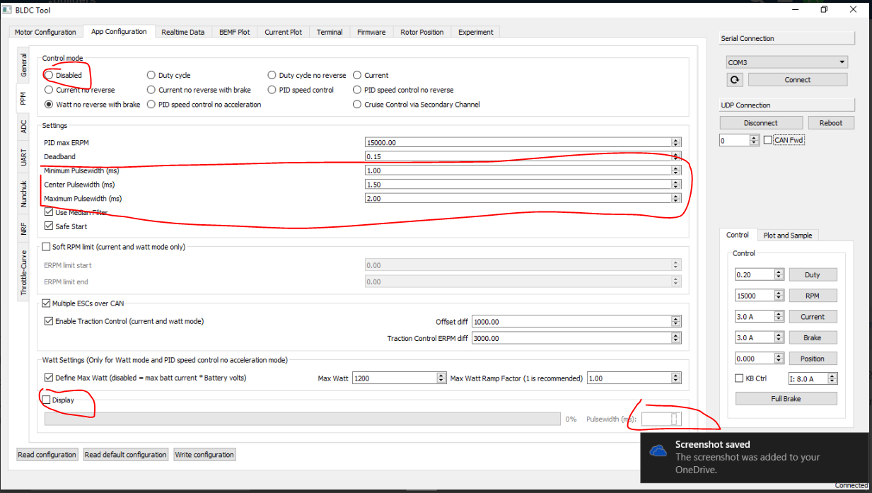
I’ve gotten most of the hardware installed and enclosure made. Electronics wired. I’m wanting to do @Ackmaniac 's watt control mode version of the VESC firmware and this is where I’m hitting information overload. I have watched the VESC firmware tutorials until I can’t see straight.

I have updated the firmware. no problem there.

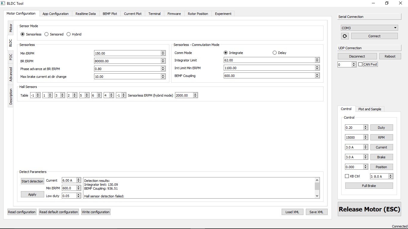
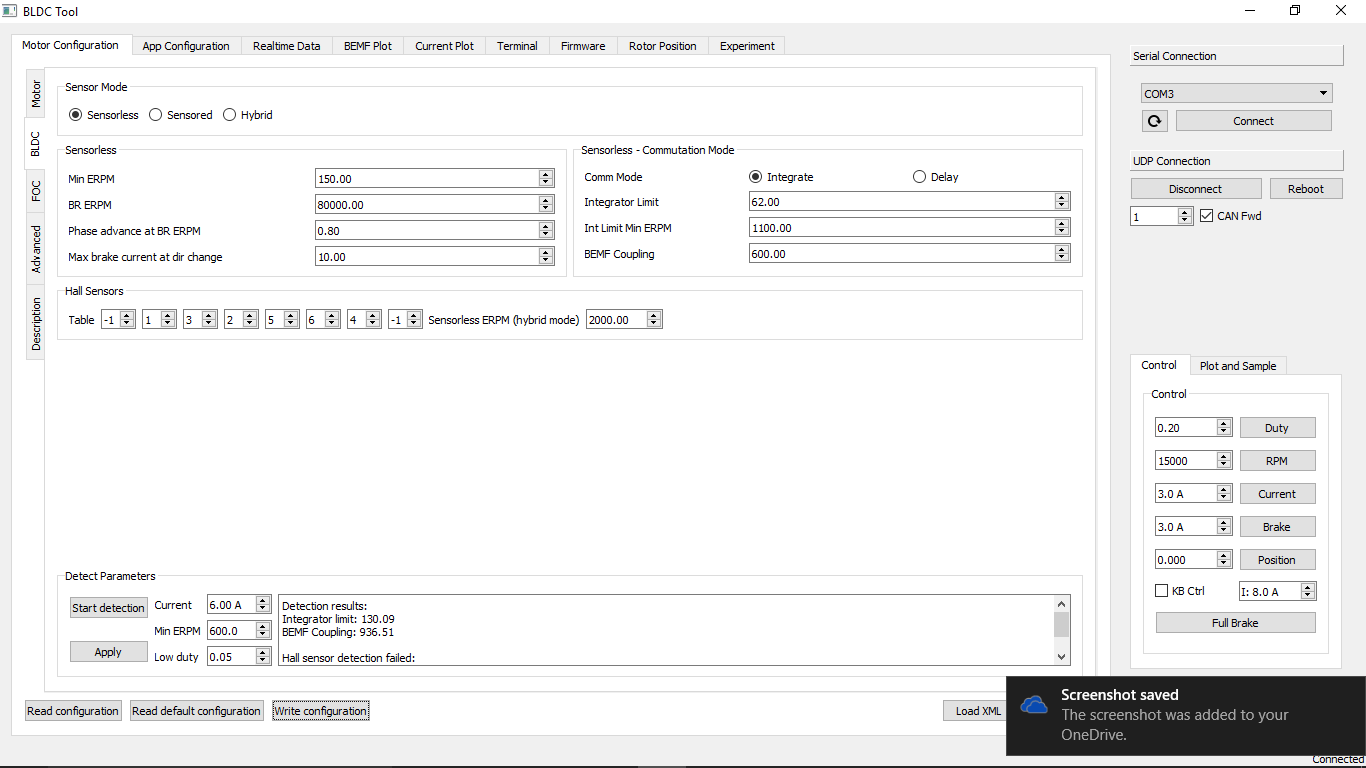
Motors detected and seem to be fine, but when detecting hall sensors is says failed. I rewired the sensor wires in order (as far as I know they are correctly connected to VESC, but I would like a confirmation).

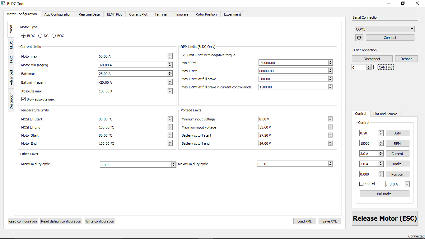
Too many numbers to for setting limits. I’m just confused here. I follow ESK8 supports video, but get confused every time he mentions hub motors and dont change this or that, I would really appreciate some simple settings for Dual 6354 (from @JLabs Group buy) and Dual Vesc Settings with 8s 20c lipos.

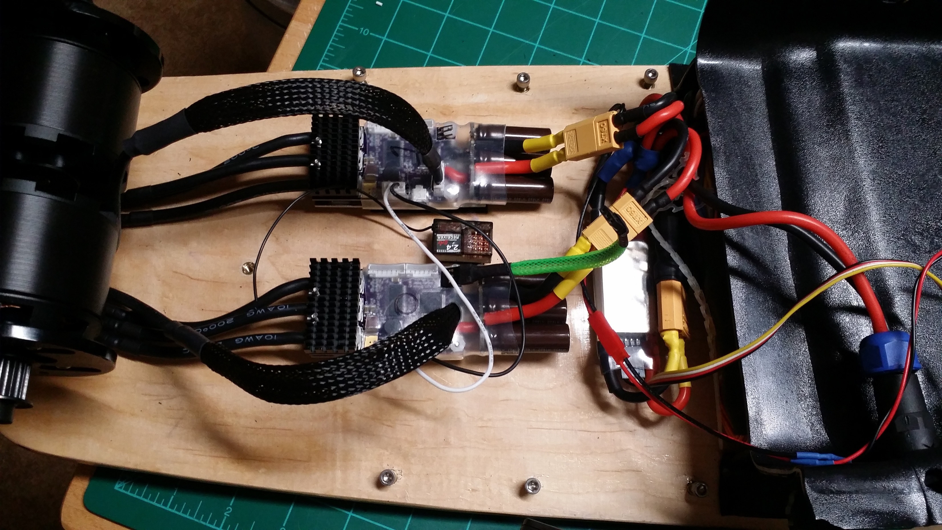
Uploading a few pics of build now and could upload VESC setting screenshots, but they are DEEFAULT @Ackmaniac 2.52 settings right now EXCEPT for controller ID set to 0(the one with the ppm receiver attached) and 1(the other one).

I do have a BTLE 4.0 nano board I would like to hook up, but can’t remember where I saw the thread and the information to hook it up correctly.

Thanks for anyone that helps, I will greatly appreciate any insights I can get.

1 Like

I bind and test the remotes before sending so you should have received it plug and play. Make sure you have the cable plugged into channel 2 in the correct orientation, and then power on the receiver.

  1. Turn off the controller
  2. Hold in the bind or pair button on the remote
  3. Power on the remote
  4. Release the bind button when the led inside the receiver blinks
  5. Your all paired and ready to go (there are also paper instructions included in the package)

THANK YOU!! I was trying to bind it using the bind plug. Definitely Connected now. On to VESC Settings.

OK Some Preliminary VESC Settings… VESC 0 / Motor 0

Vesc 1 / Motor 1

Sorry i did not read the whole thread, but set your max input voltage to 57V, on both vescs

Even with 8s? Thought it’s 8 * 4.2 = 33.6

It’s safer because if you have a voltage spike it could shutdown your board. Also, the vesc’s maximum input voltage is 57v so why not?

Always, it is a safety feature that seems to cause more problems than prevents them

OK i get it… 57 is the max the VESC will take, even though My batts will only give 33.6. Gotcha.

Maximuim Input Voltage set to 57.00v on BOTH VESCs. :+1:

Solved Battery Capacity Monitor. Bad Wiring Leads

Now. Hall Sensor Wires. Any Pointers??? :nerd:

2 Likes

It’s Alive!! Alive!!!

OK. Most is working, just want to be sure my settings are correct before I try to ride it.
Left off Sensor wires and kept it in sensor-less. Would like to run Sensor-ed FOC but I need to understand those settings first.

Thanks for the all the inspiration and help from the community, If it looks like I took an idea from someone, I did. None of the ideas I had for the board were mine originally, I just picked and chose what I thought would work. Again – this couldn’t have been possible without this forum. Sincerely, Thanks. :joy:

2 Likes

Nice job looking really good!!!

Thanks!
Not to proud of the enclosure, except - - I made it! Really sloppy compared to others, but maybe that’ll get a redo. Again, thanks for bringing the parts together.

Do the motor detection correctly. You have to run the motor detection and afterwards you have to press the apply button. Then you have to press the “Write Configuration” Button. But you have to disbale the PPM control mode for that. Otherwise your remote would disturb the motor detection. maybe that was also the reason for the wrong hall sensor detection. Correct values in your case would be Integrator limit = 130 and BEMF Coupling = 900

And your battery cutoff start and end is a bit too low for lipos. I recommend to strat the ctoff at 3,6V (8S * 3,6V = 28,8V) and set the end to 3,4V (8S * 3,4V = 27,2V) per cell. Li-ion batterys could go lower. And you should adjust your PPM Pulsewith settings. Because i don’t think that the standard ones are correct. First set the Control mode to disabled. Then active the Display checkbox. So you will see the PPM signal from your controller. Then set the center Pulsewidth to the value that stands there when you don’t touch the throttle on the remote. Then the minimum to the value when you brake fully and the maximum to the value when you give full throttle. Don’t forget to write these settings and activate the Watt control mode again.