I’m going to build a few of these if anyone is interested pm me. These things look awesome, thanks @solidgeek
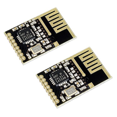
For anyone that want to switch to a smaller NRF24L01+
 It shorter than the ceramic one and less power consumption.
1 Like
I personally used this module on both receiver and Transmitter and I get stronger signal within 5m between walls. Didn’t test outside, i guess it would be more. It’s also smaller than nrf24 ceramic module.

adding code for auto stop to a reciever is a good idea. incase of lost connection between TX and RX. your board will slow itself to stop.
I’m gong to wholeheartedly disagree with that.
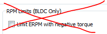
The reason we all get rid of ‘Limit ERPM with Negative Torque’ is because you begin by flying off the board and end by looking for your teeth, same situation if you apply negative torque on disconnect :).
1 Like
What I meant is applying the negative torque slowly 10+ seconds from Neutral to stop. Enough time to brace yourself. And that is only applied when the Controller WAS connected.
I see it working but it would need more precise feedback algorithm, probably one that Benjamin is going to work on soon (as Frank says will be better than anything out there and easily better than watt mode). Hope it’s true, for now I’m with @mmaner.
1 Like
If anybody is interested in the schematic here’s a link to the file. You’ll notice I’ve used a different battery to the one used by solidgeeks. If you want to use another battery you’ll have to tweak the sense resistor value but that’s in the datasheet for the charge controller
Like I said earlier this is a very simple design, it’s based off an ATTiny85 and outputs just the PWM as personally I’m not interested in the telemetry data. I’m interested in just going and stopping ![]()
I’ve ordered some boards which should arrive in a few weeks. I’d post the .brd file but until I can guarantee it works I don’t want to waste anybody’s time.
Price works out to ~£25 but there’s a lot of soldering involved. Will post some pics as I go if anyone is interested
Hello, I have been using it for a while. But I think its Generate address has a bit of a problem. It will switch values immediately. Sometimes there is no response, can anyone tell me why? Still my operation problem. How can I deal with this problem? I want to make it better
So is not synchronizing to the RX? because TX and have to get RX to change its address pipe and send back confirmation back to TX first before the TX can take effect. I have added a fix to the code.
I also added the auto deacceleration to STOP the board from running away if the controller is disconnected whilst riding. The code will apply brake slowly until it reach a minimum throtlle. And after 30 sec the code will set the throttle back to neutral position.
3 profiles for each controller. Now you can use only one controller for 3 different boards and settings 
2 Likes
My receiver has received a signal, but sometimes it can be changed at once, sometimes for a long time. My receiver is always on. A new address cannot be generated after using the “Generate Address” multiple times. Is it only me that one person has this problem?
Try out my code. basicly is a copy from solidgeek with a few changes. See if you are still experiencing problem.
1 Like
Hmm I don’t see any links to your repository/file. Where can I find your code?
Very nice code. I will look more into it in the morning. Btw, function uint64ToString is actually not properly defined… But since upper 32 bits are always 0 for this use case, it doent show any errors
My receiver isn’t connecting now.
Here is the serial output from the receiver: ** Esk8-remote receiver ** Settings loaded Printing receiver details STATUS = 0x00 RX_DR=0 TX_DS=0 MAX_RT=0 RX_P_NO=0 TX_FULL=0 RX_ADDR_P0-1 = 0x0000000000 0x0000000000 RX_ADDR_P2-5 = 0x00 0x00 0x00 0x00 TX_ADDR = 0x0000000000 RX_PW_P0-6 = 0x00 0x00 0x00 0x00 0x00 0x00 EN_AA = 0x00 EN_RXADDR = 0x00 RF_CH = 0x00 RF_SETUP = 0x00 CONFIG = 0x00 DYNPD/FEATURE = 0x00 0x00 Data Rate = 1MBPS Model = nRF24L01 CRC Length = Disabled PA Power = PA_MIN Setup complete - begin listening New package: ‘0-0-0’ Getting VESC data New package: ‘0-0-0’
Transmitter: STATUS = 0x0e RX_DR=0 TX_DS=0 MAX_RT=0 RX_P_NO=7 TX_FULL=0 RX_ADDR_P0-1 = 0xe8e8f0f0e1 0xc2c2c2c2c2 RX_ADDR_P2-5 = 0xc3 0xc4 0xc5 0xc6 TX_ADDR = 0xe8e8f0f0e1 RX_PW_P0-6 = 0x20 0x00 0x00 0x00 0x00 0x00 EN_AA = 0x3f EN_RXADDR = 0x03 RF_CH = 0x6c RF_SETUP = 0x07 CONFIG = 0x0e DYNPD/FEATURE = 0x3f 0x06 Data Rate = 1MBPS Model = nRF24L01+ CRC Length = 16 bits PA Power = PA_MAX e8e8f0f0e1: Failed transmission
Checked continuity on all the wires to the Nanos. Maybe a NRF is bad?
hi I tried the code for from both (solidgeek and deakbannok) and still cannot get the nrf to connect.
any pointers?
the wireless icon on the screen flashes constantly

 gear ratio = WheelPulley / MotorPulley.
Although the process is correct, I think your name is easy to misunderstand others.
gear ratio = WheelPulley / MotorPulley.
Although the process is correct, I think your name is easy to misunderstand others.
Can anyone tell me the calculation principle of speed and distance, whether there is any reference material?
HI, did you get yours to work. I have 3 nrf modules and tried all interchanging all 3 without any luck, I cannot get them to connect receiver/transmitter! spent almost half a day doing tests and rewiring…
any help is welcome.