No problem. We all have our tired moments.  I will try to toy around with soldering on my sacrificial motor before I ditch the soldering idea.
For the love of skatan I can’t get my wire ends clean enough to solder without messing up the windings inside the motor. I am running out of sacrificial motor cable length. I will need to remove the enamel either way, solder or crimp…
I tried to use a sharp xacto knife, sandpaper, acetone, none cut it(get it…) to a degree I want without causing my further down strands to heat to 180+'C which in turn melts internal enamel and will definitely cause either extreme stiffness or shorts.
Any better ideas on how to(home conditions preferably)?
Could you hold it tight in a vice/pliers and use a Dremel with a cutoff wheel to remove the enamel?
I doubt it. Maybe I could just try and heat through it when I sand off some of the enamel, just wonder how sensitive the windings are on SK3s… Yet on my sacrificial motor I have seen winding temperature of 180’C, gradually creeping down inside the motor and staying at 90’C there. Stuff’s creepy…
Also - you can take a pair of needle nose or other pliers(or any metal clamp) and affix them to the wire down the line if there’s still enough slack to act as a heatsink so the internal wires don’t get as hot.
The heatshrink will not allow it, that’s the problem keeping me off from using a heatsink… I could of course try and blow some air with a blower fan…
Alright, it’s officially time for bed for me. I was wondering why the idea of hestsinking was coming to my mind. I knew I had just recently learned of it. Was it possibly because it was already mentioned in the thread? Yup, that’s fuckin why lmfao.
That aside - I guess I’m really glad I bought maytechs now? My wires are like, nice and silicone stranded haha. I don’t even know what you’re really dealing with tbh
1 Like
I guess that’s what I get for grabbing 3 SK3s for 35€ each to my door… 
Too cheap and brand new to be ruined by bad soldering skills.
With last lengths of wire I’ve found two major tricks.
Cleaning the “enamel” which is apparently some sort of polyurethane (250’C+ melt point) takes just thin pliers with ridges and fanning out the cables.
Flux. Lots of flux. Flux the CRAP out of the motor cables and keep conservative at the silicone ones as that puppy will absorb ALL the solder QUICK.
Anyways, I will try the real deal soon. I have one motor to pop I guess…
1 Like
similar conversation ongoing here
There’s a link to a cool power tool for stripping enamel
2 Likes
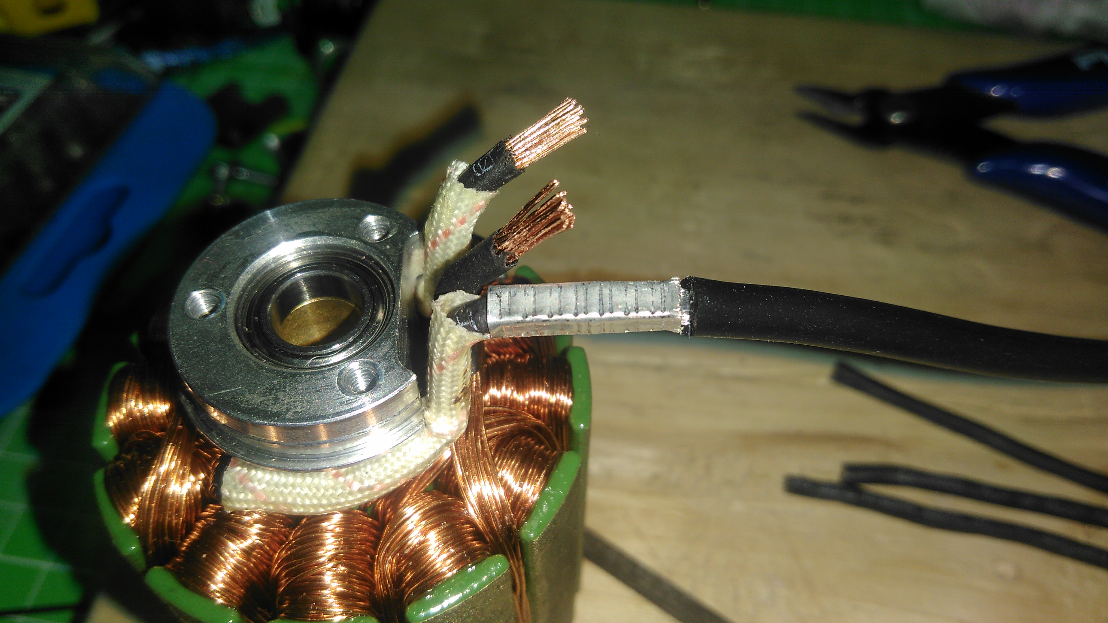
In the end I just went on with crimping, because none of my soldering attempts did it. Mind you, a professional at his field tried it and said that the copper in the windings transfers heat too fast and basically soldering will not form a “legit” joint unless you burn a lot of enamel in the process. Always a cold/semi cold joint if you go without melting the enamel or stiffening the windings from heat. This explains the 4-5 centimeters of solid solder wicked windings at the bullet connectors at these motors originally:
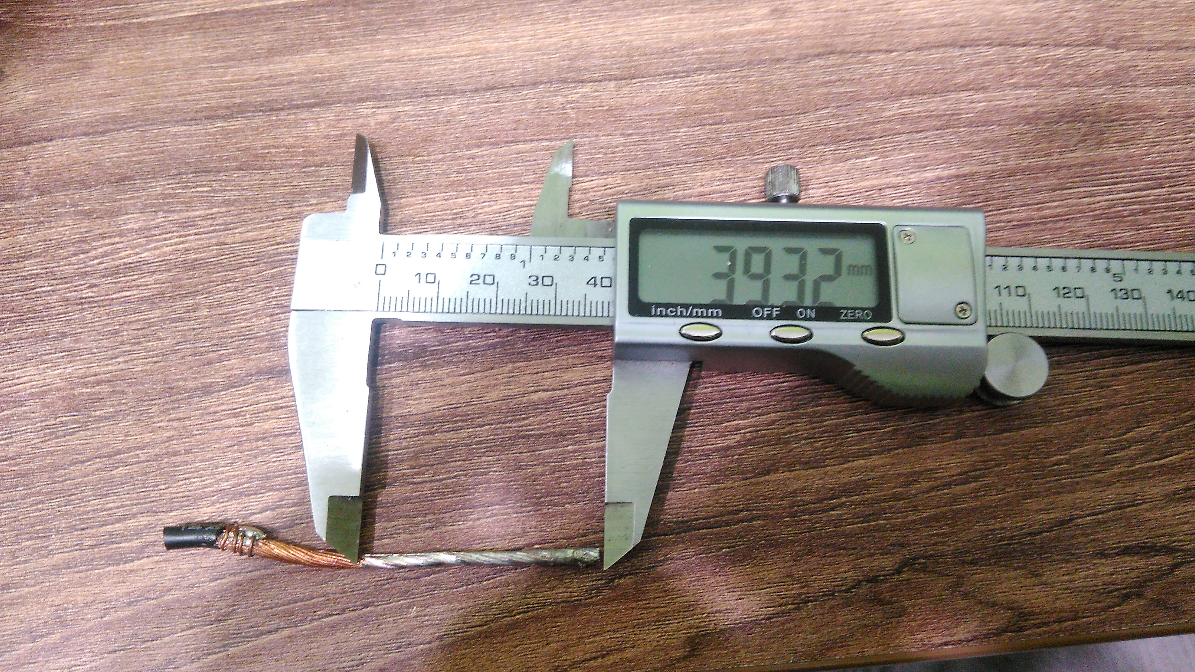
I used tinned copper ferrules and had to remove their plastic housings(I couldn’t find the uninsulated version to buy). They fit 12AWG and the windings perfectly with space for wire butting left. I also used the crimps on the budget just for that kind of crimping:
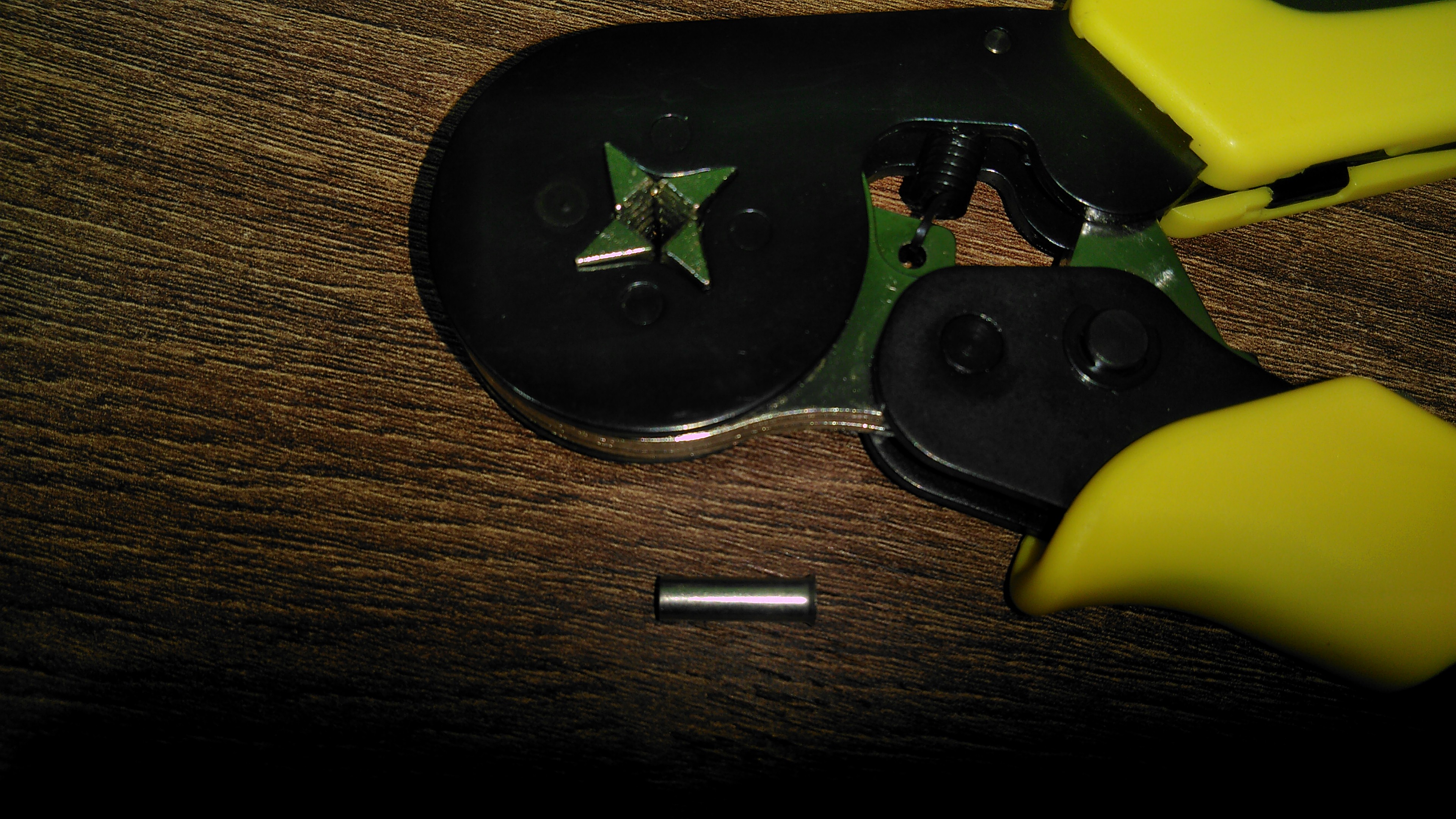
These leave a square crimp with ridges and pretty much push all the air out and compresses the cables to insane contact.
I cut windings after motor disassembly to leave ~1cm of uncut winding after the bend, then stripped 5mm of the windings:
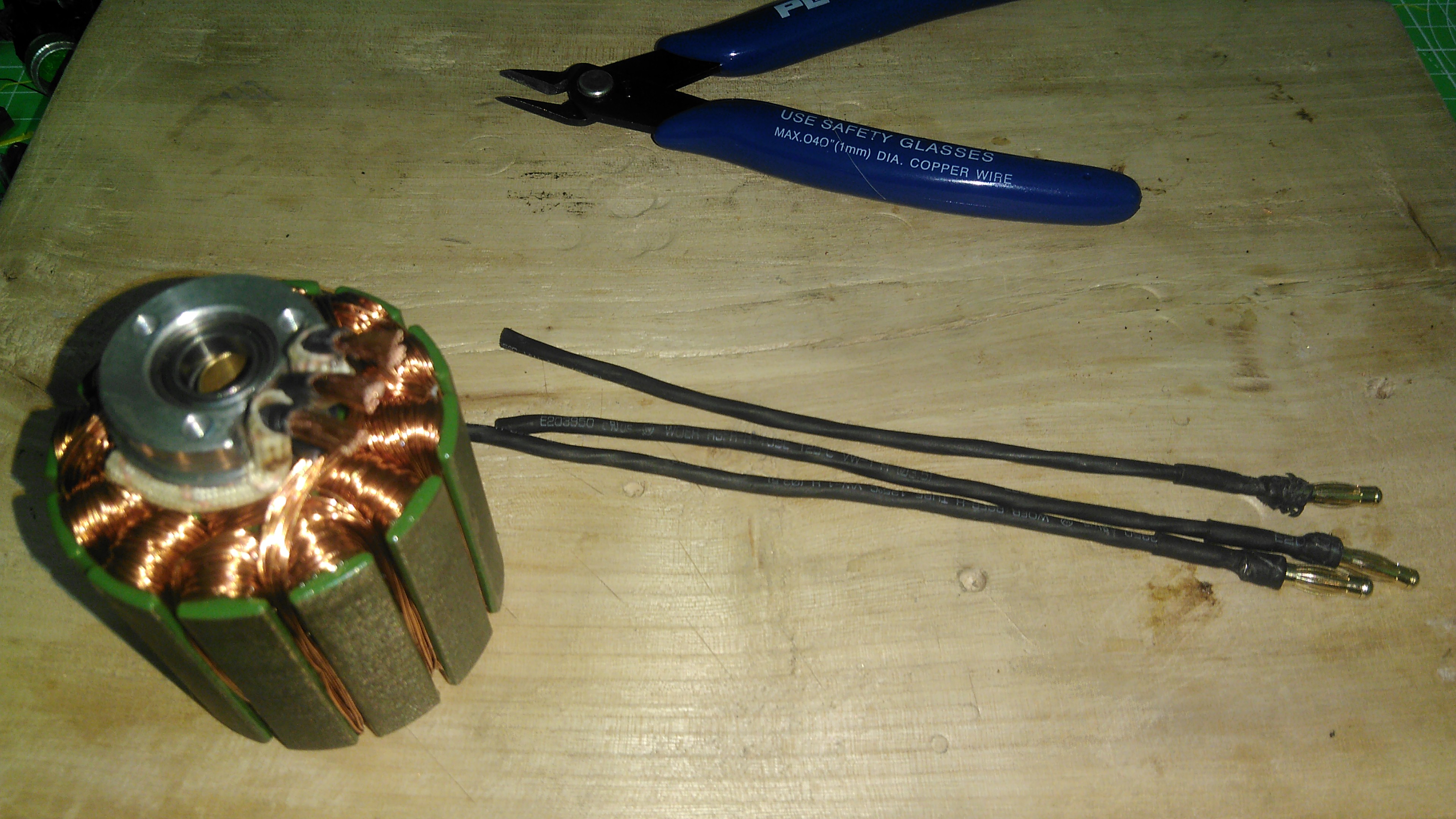
Scraped the enamel(very tedious with so little windings, but doable):
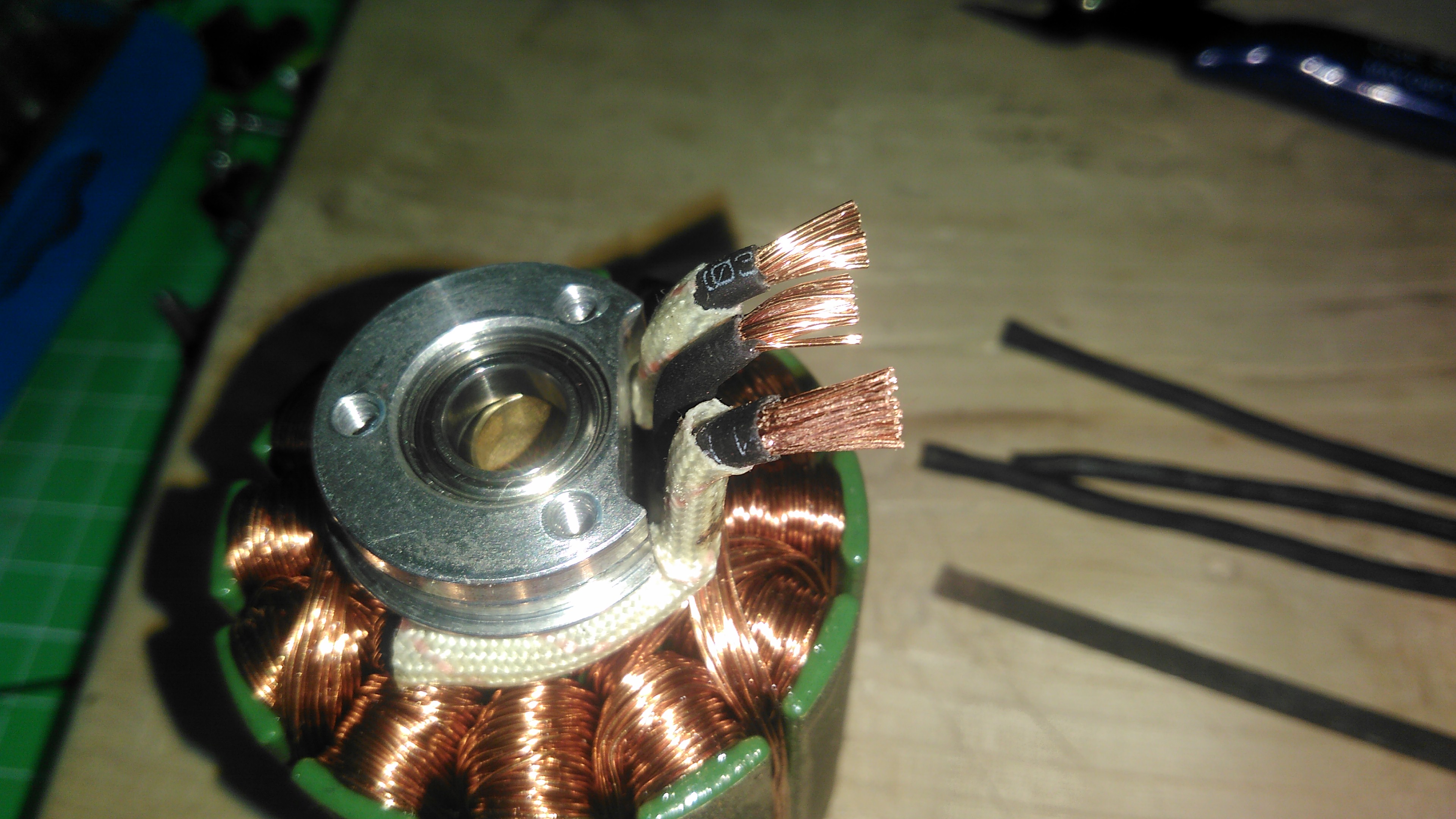
Pushed the 12AWG into the ferrule, pushed them together onto motor winding part with as much force as possible as it allows the cables to go into each other, then crimped the HECK out of them, creating a solid joint:
The end result:


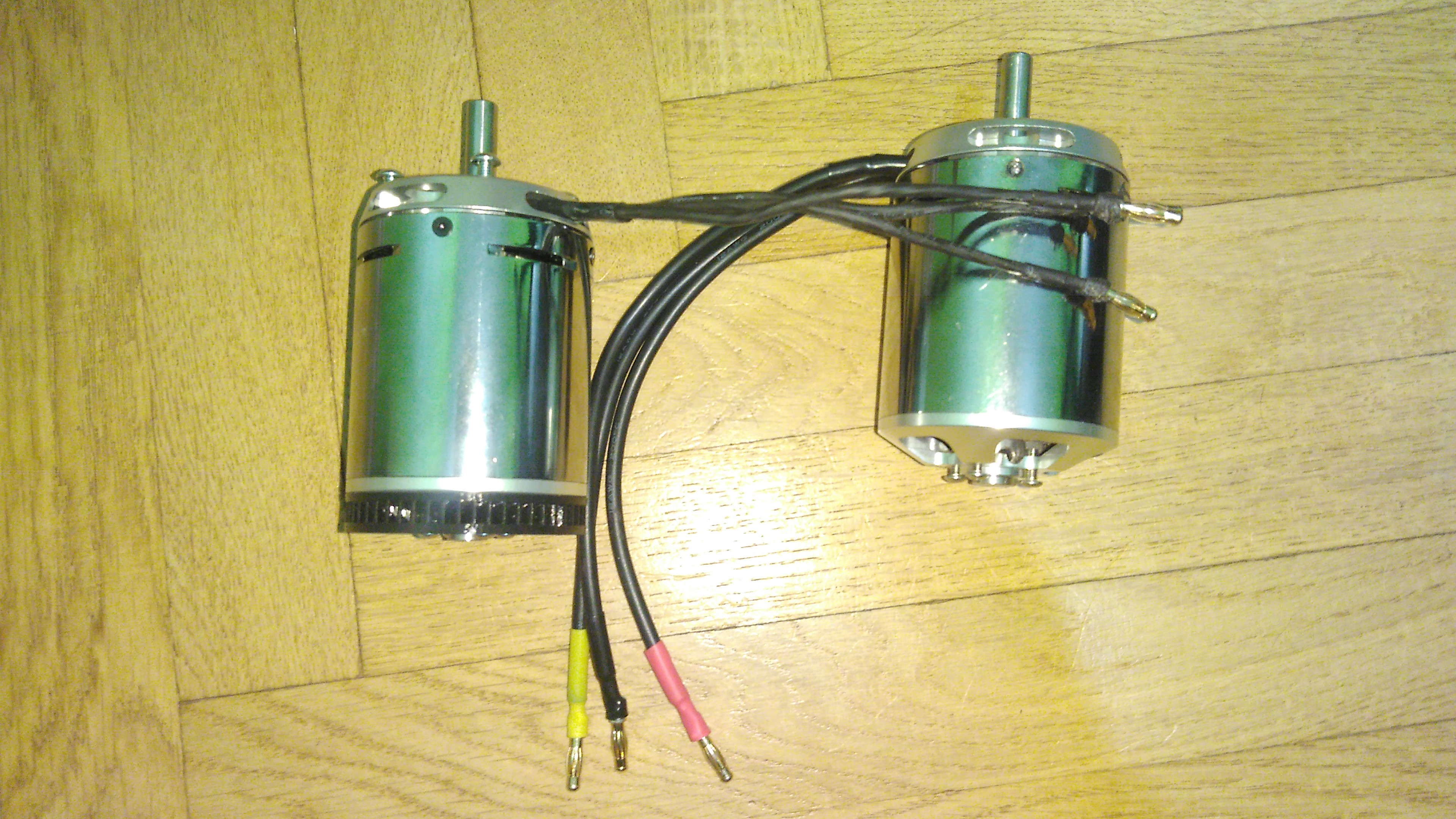
This one is my semi-sacrificial motor. A little bit beat up, but it’s going with a VESC with 4(4.5?,5?)mm bullets. The standard SK3 ones which I just salvaged from original cables I cut.
The same procedure will be used for my Unity motors. Hope it helps anybody who searches!
Later I might add a little bit more pictures showing more of the process to this post.
Cheers!
Nice!! Very difficult work, having a similar experience myself, but much longer phase leads to work with. I’d love to see the motor IR measurements (maybe even a before/after?) when you get around to configuring your esc settings! Persistence is the only thing that can get through wire enamel apparently, there really isn’t a shortcut.
That’s for sure. ![]()
If unity can spin only one motor during motor detection, I could see the difference in motor resistances for sure… ![]()
1 Like
Look at the left record.
Original motor with original leads:
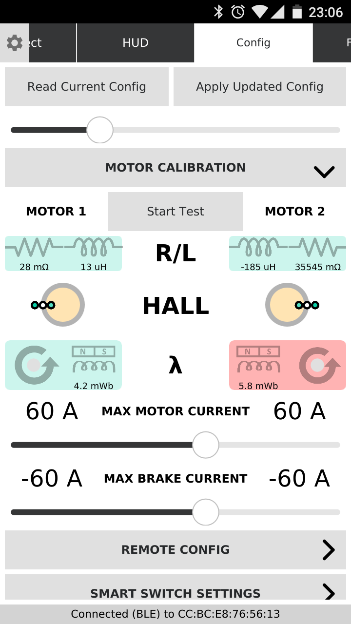
Motor with changed leads:

Both are 168kV SK3.
1 Like
Crap, I feel outdated. I don’t know exactly what I’m looking at there; Why does motor 2 show 35545mOhms? Am I misinterpreting? Stupid Unity and it’s fancy streamlined readouts. So jealous, but so set in my ways. I digress- the left half of your screenshot makes sense to me, but the other side… IDK
On a side note, as per @deucesdown 's suggestion, The only way I’ve been able to penetrate (lol) the enamel on my mto6880 phases is with a solder pot. A 150W, no temp control, hot as a mother f*cker, solder pot. Having read your post sufficiently to reply here @murloc992 , I know that the pot would not work for you due to the length of your phases and the thermals of copper.
Anyways, looking at the above data, I either don’t have a clue what I’m seeing, or that’s a thousand times higher resistance…? Am I an idiot, or what? What does the red mean? Thanks for the (potentially misunderstood) data!!
The right record is the second motor, which is not connected. ![]()
The resistance is the same(even though leads differ in length by 10+ CM), only micro henries and mili webbers are different by one(.1 for webbers), no idea of their impact.
1 Like
So that means you have a sound and reliable electrical connection I hope? It would be amazing to know if crimping were a viable solution to this!
I was literally ordered to crimp the connections by people who work with all sorts of electronics for more than 20 years. They say if you do it properly, you get a gastight(airtight) “weld” of copper from the pressure.
Heck, I even tried to crimp a phase lead without removing enamel and I still got continuity, I do not recommend doing this ofc, but the pressure is enough to make it(the enamel) shatter.
1 Like
That’s what I’ve read too!! Very excited to see your success with that method! Cheers!!
1 Like