I’m getting ready to make a 12s6p battery, and I made a 3d model to try and show my proposed layout to get some feedback on it:
Each part of the 12 series is a collection of 6 cells, connected together in parallel in a 2x3 config. The series snakes out and back from the terminals. Each series in upside down of the one before it so that nickel strips can be welded on from one series straight across to the next one. The squares on top of the pack represent where the strips are connecting series together. It might be hard to see, but there are some on the bottom of the pack as well that continue the snaking pattern.
The primary goal of this layout is to eliminate any head to toe connections that would result in nickel strips being bend.
All connections will be made with a spot welder, and the terminal leads will be soldered onto the nickel strips before being welded to the pack.
Also! I’m planning on drawing 100 amps from this 12s pack. And want to make sure I have enough layers of nickel. My strips are 8mm x 0.15mm for a cross-section of 1.2mm² per layer of nickel. I plan on making ‘ladders’ on positive an negative terminals of each of the 12 segments like this:
For the parallel connections, it should be enough from what I’ve heard. I used wayyy more in my pack but other people haven’t had issues with how much you are using.
For the series connections, I would probably skip the nickel strip and only use braided copper wire. Don’t know if it’s true that it can do 32A, but if so, it should be enough while still keeping some flex in the battery.
You could also use copper strip. I have heard it should be pretty good and can draw a lot of amps (more than 100A)
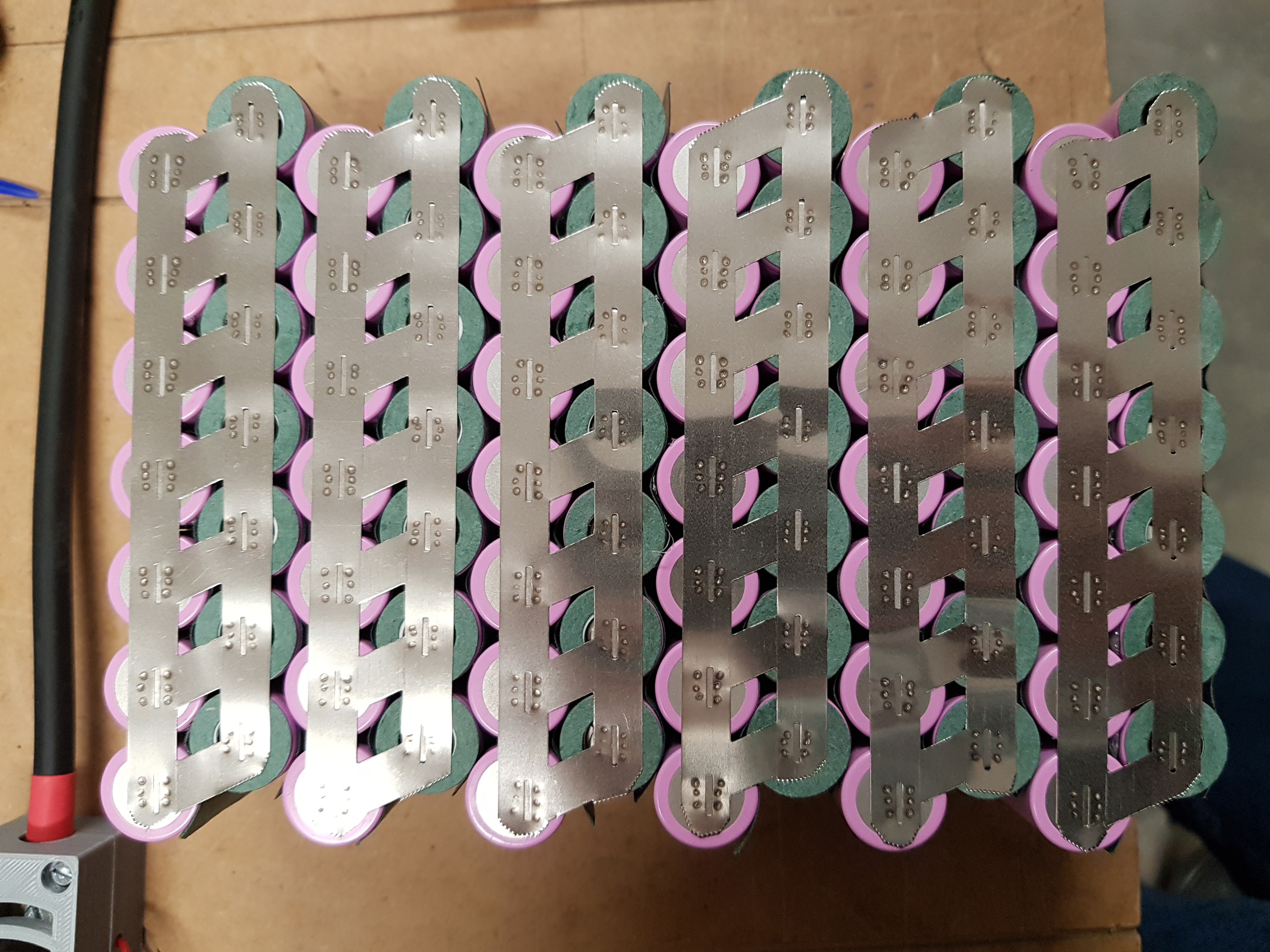
Yeah this is basically identical to my first config idea! I originally thought of 6x1 grouping similar to your 7x1 but lately I’ve been leaning towards 3x2 because that way I can have the overall positive and negative terminals next to each other rather than on opposite ends of my pelican case
Sorry to interupt the chat but i just welded part of my battery together and the left cell is 13 degrees hotter then all the other ones. I dident short it out or anything. just a bit confused
They might be balancing. Measure the voltage on the cell and the voltage on the P-pack. If they are off at all, they will immediately begin balancing (charging the lower one, discharging the higher one)
You don’t want more than a 0.1V difference and it’s better if they are the same before the weld.
Each strand of the tinned copper braid is good for 40A, so I have 3 lines of it connecting each series together. That’s fine, right?
I’ll double up on those power lines from the battery to ESC. Would it still be ok then have them conjointed back into a single 10 awg wire right before the ESC? The ESC has power input as single 10awg with a xt90 connector. Would it be fine to continue using these or should I desolder them from the ESC’s pcb and replace with something more heavy duty? (Flipsky dual)


 just a bit confused