Hi. Thanks. I’m using the Laguna IQ HHC. I agree; it’s the perfect size for this kind of thing. I think being smaller also helps make it a little stiffer, so better with aluminum. Not as good as a Tormach, I’m sure, for metals, but a good all-rounder for woods/plastics and metals.
1 Like
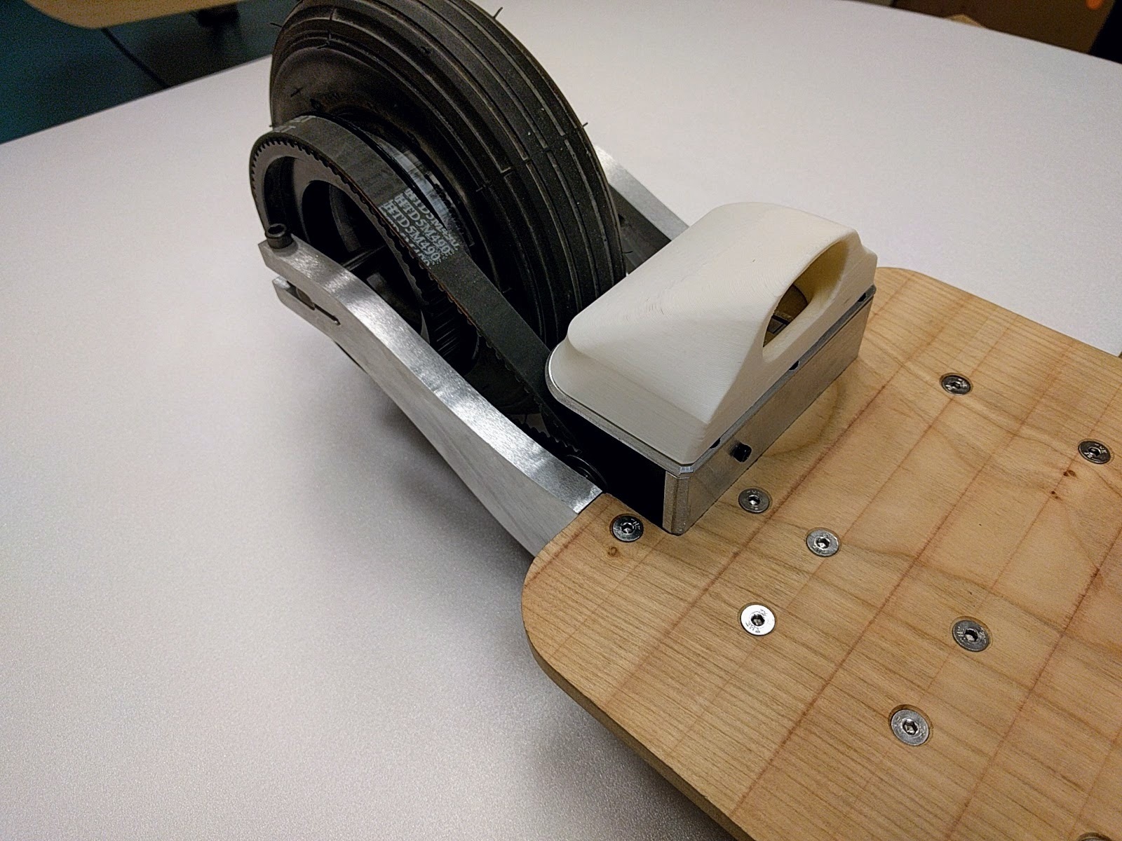
Got the motor mount assembly completed and all connected together. Feels like it’s going to be pretty sturdy. Lots of attachment points to deck. The pocket you see will hold the VESC and hopefully the receiver too. Planning on covering this whole area in 1/8" alu sheeting.
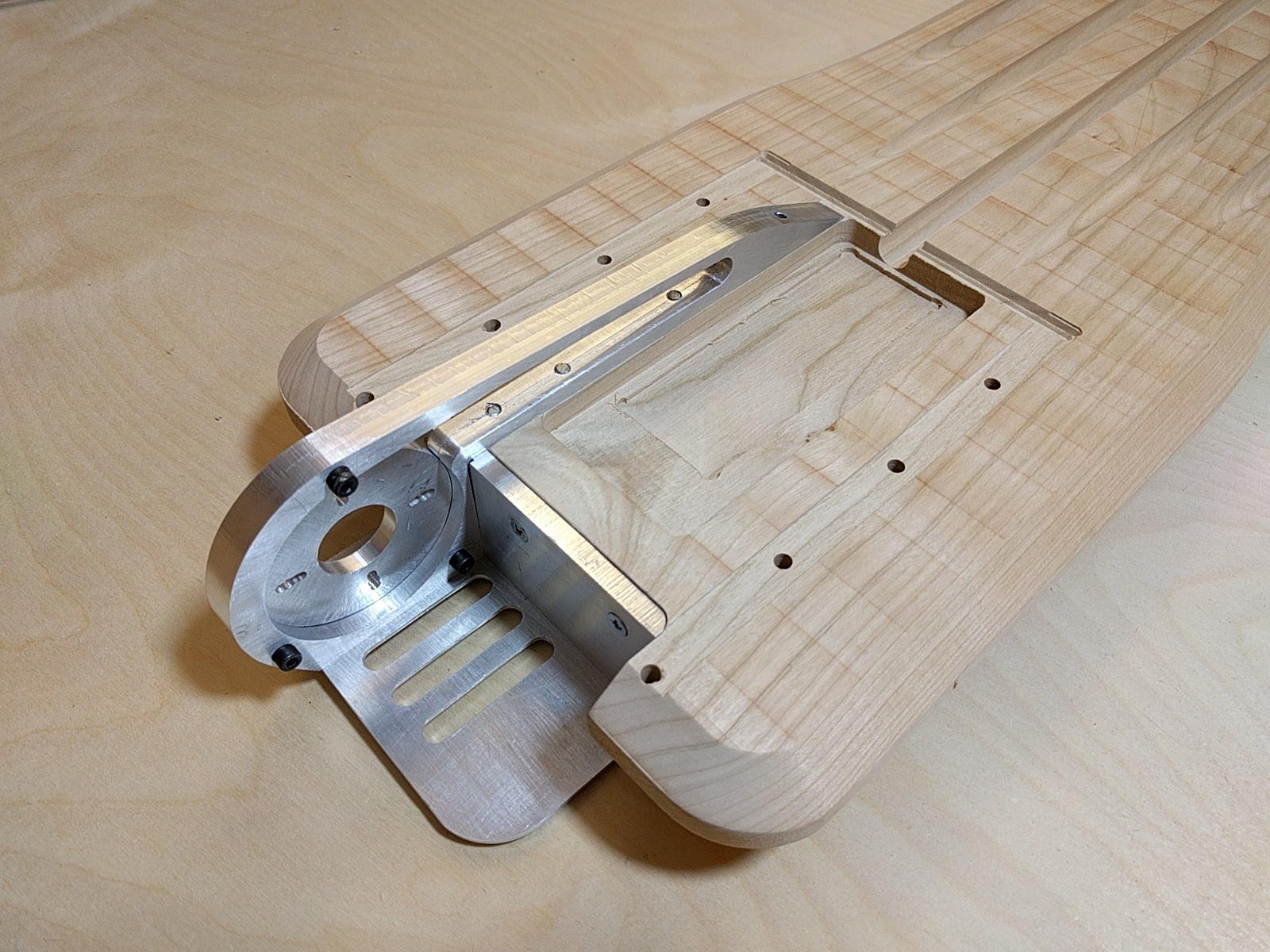
Been thinking of adding a foot grab in front in order to be able to lift front of board when needed (bumps, curbs, fashion poodles…) Any thoughts on this? Wondering if it’s just going to be painful if (when) I need to jump off the board fast. I’ve seen something similar on other boards. Also wanted to make it dual use as a handle. Seems like a pretty good place to pick up the board.
Also will be 3D printing an air scoop that should help ram air onto the motor. But really, doing it just because it looks cool.  Thoughts on the foot lift appreciated.

10 Likes
That looks really cool. Can’t wait to see how this turns out. As far as the foot grab, how about just using a pair of the freebord bindings? The one you’re proposing looks really nice integrated into the board though. I think you would just need it to be sloped a bit like a shoe so it’s more ergonomic.
Been working on the drive train assembly.
Here you can see how the VESC fits into the pocket.
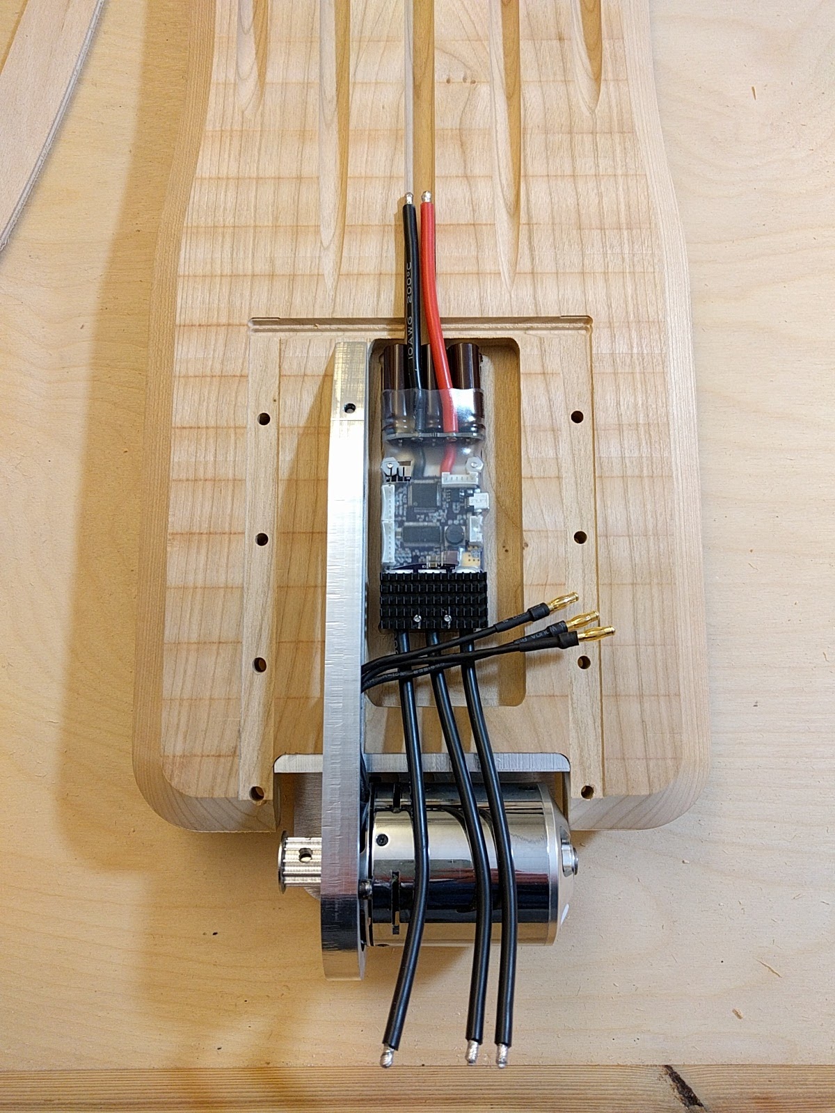
Got the struts connected to the deck. The struts will be sheeted over, covering this area. Not sure if I’m going to use ABS plastic or aluminum. The motor was longer than I had calculated in the CAD drawings so I had to remove a small pocket in the side of strut so that the end of the motor would not rub on the strut.

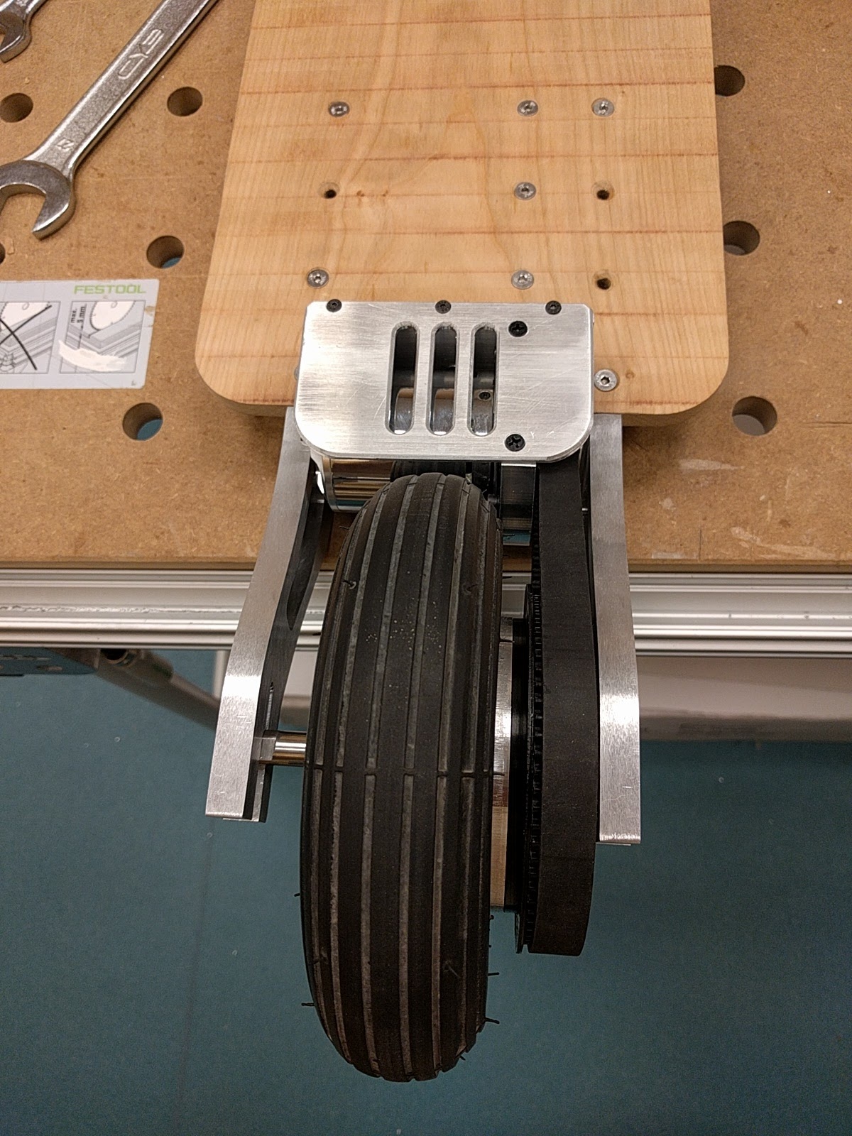
Wish I had a longer belt. Had to remove a little material from strut axle channel in order to move the wheel forward a couple mils so that the belt wouldn’t be too tight. Am using a 490mm belt. Could not find a 495 or 500 in the right width.
Had to make a spacer to move the wheel gear out to the side more, otherwise the wheel would not have been centered. 1/4 inch alu did the job.

Need to make some spacers to place on axle to keep wheel centered. Also still need to drill holes for the clamp-down bolts needed to hold the rear axle in place.
16 Likes
Good that the belt fits quite ok for you now 
Keep us updated about other details in the future then 
Been connecting many of the alu pieces together with hardware. Lots of measuring, drilling and tapping.
Here’s the front assembly. Still waiting for the correct size shoulder bolts. The ones I ordered before were a little short. Some of the bushings seem a little tight around the shoulder bolts I do have. Not sure of the best way to create a little more room in there. Tried drilling one out and adding some oil. Better but not great. Seems like this assembly needs to be very low friction but maybe not…

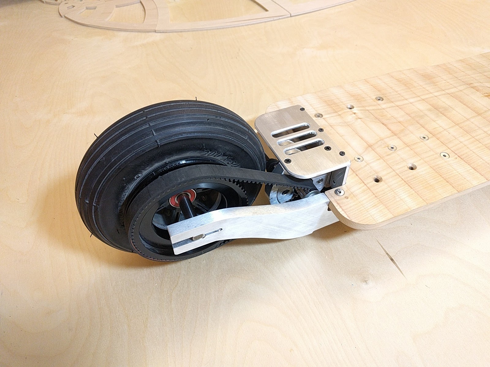
A view of the back with clamp bolts on rear axle and 3d printed air scoop for motor.
Bottom, rear. Went with some ABS plastic sheeting to cover vesc pocket.

All struts screwed into place.

20 Likes
Sexy build man. Well done!!
1 Like
that’s clearly a masterpiece. impressed !
1 Like
Coming along nicely! So it happens that I finished almost every part of mine build yesterday, I will post a thread tonight  All that’s left for me is to bead blast aluminium parts and get them anodised black.
@bill_f As for the front assembly, I leave my tight, bushings will wear out after time, and consider that roughly 40 kg force will be making whole thing to turn, a little friction won’t be a problem in this case, I think that it also may help at high speeds. Just one more thing, You put those bushings and front linkages opposite than they’re supposed to I think. The shoulder of those bushings should be facing inwards, to create a low friction surface, I left mine protruding 1mm above surface of linkages, I noticed vertigo did the same in his build.
1 Like
Thanks for the tips. Yeah, I’m trying to figure out the frictional forces on this assembly. Since I still don’t have the shoulder bolts, can’t get real feedback yet. But what you said makes sense. I didn’t notice the direction of the bushings in Vertigo’s build. I’ll also move them out maybe half a mil, like you suggested. I don’t have a lot of room in there but I can always make more space if needed. Interested in seeing what you have designed and built!
Well, You can just check that out  http://www.electric-skateboard.builders/t/diy-electric-caster-board-emax-gt5345-maytech-12s-esc-10s-10ah/18902
1 Like
I can comment on how that board (edit: YiiBoard) preforms (mine is being shipped right now, but I got to test drive one back in Dec), You can see by the specs it’s by no means a fast board. For me though it was all about speed, I could tell that the faster I went the more stable it was, but it was also extremely stable at low speed. There is a bit of balancing you have to do, and I found it awkward that the board doesn’t fight when you bank it (no bushings obviously). What I noticed though is that while the board is pretty high (and makes it difficult to get up on before you set off) that height helps it to be stable, at low speed if I wobbled too much during a tight turn, I had enough clearance to keep from bottoming out. This allowed me to stay on the board and apply more throttle to pull myself out of a turn that would have likely stopped me. Much like a motorcycle or dirtbike, the act of adding power helps to self right the vehicle and keep from falling over. The guy who had been ridding it for several months said I was quicker than anyone to pick it up. He thinks it maybe due to my background in skateboarding / natural balance, I think it’s because I was afraid to be aggressive on the throttle.
I think it has a lot to do though with the fact that the wheel is behind the caster, (unlike on a bike where the “caster” is more behind the wheel) that when you add more speed it wants to pull the wheel straight. So with this really cool design I don’t know if your “caster” would work the same way, or if it would work more like a bike / scooter.
2 Likes
How is Your build going? Any updates?
1 Like
Hi. Had to wait for some shoulder bolts to arrive from China. Made some progress on the steering mechanism. Drilling and tapping holes is going pretty slow. Haven’t been able to get the shoulder blocks totally perpendicular so needed to do some modifying of bolts so that there is smooth travel. Need to create holes for shoulder bolts on front struts next, which should be interesting since they are at 15 degrees. Probably will create some kind of jig out of MDF to hold things perpendicular although haven’t had much luck with the jig I made for the CNC for the other parts (the small blocks that connect to the front axle).
How’s the riding coming along? Is it getting easier? Any modifications?
After watching your video, I’m a little afraid to get on this thing. 

2 Likes
Nope, no modifications yet, I kinda manage to ride it straight and do slight carving just for now. You can see in my thread I picked up parts from anodizing and put all of this together.
Starting to ride on this thing is the hardest part, from there it should get easier and easier as You gain speed, my advice, don’t be afraid to go fast and obviously wear full protection.
Vacuum Forming
(Getting close to riding this thing. Just need to do some soldering to connect VESC and pwr, and final adjustments.)
Going with my second design for battery enclosure. First one looked too much like a granny toaster.
The toaster with plastic (that I had to cut in order to get off mold)

Rendering below shows what I was going for. 3d printed a hoop that connects to board. Enclosure sits on top of it, holding it in place. Still not sure how to secure it. Maybe magnets. Maybe a vertical bolt. Don't want any rattle, and with heavy batts, needs to be pretty secure.

Had to make mold first. Here you see the mold with the roughing passes done. Learned after making the toaster that I needed more draft angle so that plastic could be easily removed from mold. This one worked well.

After finishing passes and light sanding.

One of the biggest challenges seems to be how to cut the part from the excess plastic. I decided to use the CNC to cut it off. Worked OK. Should have offset the cut a mil or two beyond the original shape. Came out nice and even on bottom though (planar), which is the main thing I wanted.


Final part showing 3d printed hoop skirt which will be attached to deck. Fit is good. Pyramidal shape means enclosure gets tighter as it's pushed down. Used 4 mm ABS for enclosure. Feels nice and solid.

Final position on deck

10 Likes
This is the sickest thing iv seen all year:+1:
Glad to see You make progress in this build! I was really curious how it was going. Can’t wait to hear what You have to say about riding it
Did you use normal vacuum cleaner to form enclosures? I must say You nailed it 
Slowly coming along. If I get my butt in gear I might have it ridable in a couple days although I see rain in the forecast. I used a formech vacuum former (300 XQ). Took a few tries to get the plastic at the right temp, but after that, it’s pretty easy. I like the final product compared to 3d printing but it’s time consuming making the mold. Thinking of putting the same batt case on my other ride (which has been taking a lot of my time as I try to figure out the weak motor issue). I see you’ve been having ESC issues with your 4-wheeler as well.
discovered this thread just now - its amazing! i envy 3D modeler with cnc access - you bring diy to a whole different level! i need to get into that someday!!
also love your sense for aesthetics - beautiful details, nice pictures 
1 Like