Ohhhhh this doesn’t use a momentary switch and precharges through the switch itself. Interesting design! 
3 Likes
Something like this would be a perfect toggle switch :). Contacts are rated for 3A 250VDC.
My first iteration didn’t have precharge, the pair of IPP029N06N blew up immediately XD.

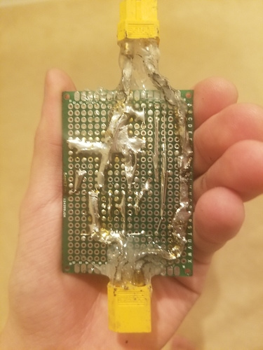
Prototype employing roughly the same schematic. Worked in my mountainboard until I moved over to the LTC7004. Switch was soldered directly to the terminals on the board.
3 Likes
Can we possibly get this with push to start? Would be so damn cool!
1 Like
Impossible with this design.
Roll-to-start and auto-turn-off design is coming in May. May not even need a pushbutton hehe.
I would strongly suggest referring to that as “roll-to-start”. “Push” is what you do when you operate the switch.
My mistake, did not realize that, thanks.
Any chance to make it with a momentary soft latch switch circuit ? Nice work.
It would need a 555 timer as toggle latch. This would add many more components and make the switch more expensive and potentially less reliable.
1 Like
You’d really need an MCU for that. It might be able to be done with a single latch, but an MCU would work much better. I like this current design, it’s innovative 
4.0V delta I think is a tad too high but I am curious to see how it works
1 Like
Worked for 20+ cycles, I’ll experiment with larger sized zener diodes once I spin out more prototypes in the next week or two. On the first prototype, using larger zeners, I ran into problems with the main MOSFETs not turning on. 4V delta (probably lower honestly) with 6,000uF of load capacitance results in 100mJ of energy dissipated, well below the avalanche energy rating of the MOSFETs
1 Like
My 2 cents here that everyone needs to keep in mind is that power dissipation is Volts*Amps. With the linear ramping of the gate we must keep in mind that at the beginning the voltage drop accross the FET is the full battery voltage. The total energy of the turn on event remains constant since you are charging a fixed capacitance to a fixed voltage. So at the very beginning of the turn on event say you are 10s full charge that’s
42V * (charging amps + passive system amps)
The turn on energy is
0.5*42V*(charging amps + passive system amps)*turn on time
Every fet (even within the same batch) has a different voltage knee where the resistance plummets at a given gate voltage, because of this the parallel fet with the lowest Vgs knee due to variance handles the lionshare of the power dissipation. So your single fet must be powerful enough to handle both the instantaneous power as well as the total energy dumped from the turn on event.
The passive current draw can also become relevant for longer turn on times due to the high voltage drop. Say you had something drawing a few hundred milliamp, it ends up being 10s of watts dissipation. For instance, the buck will turn on the MCU and other peripherals when it charges above 5V, these will pull significantly more current then normal operation because the buck is stepping down from such a low voltage. So moral of the story is find a sweet spot with a slow enough turn on time to reduce peak power dissipation, but not so slow that you start dumping a lot of joules into the FET.
6 Likes
I guess it’s safe the say that the Unity power switch is bulletproof :).
Is the Unity power switch on the other side of the filter capacitors and so does not have this large turn-on inrush?
Nope it’s an anti-spark, just carefully designed with a known capacitance which means you can make it reliable.
3 Likes
Just curious, have you considered a power on-off solution purely by pulling the DRV8301 enable pins low and putting the MCU into stop mode? Power can supplied to the MCU in this state using a high voltage LDO.
@Deodand Also, did you see my post in the FOC switching frequency thread, you didn’t reply, so not sure if you saw it. Or was my post so dumb you ignored it xD.
2 Likes
I think that would subject the main battery to the filter capacitors’ leakage current.
Aren’t electrolytic capacitor leakage currents on the orders of uA though?
Yeah it comes down to leakage we did the math and it was a bit too high. Kind of on the edge like 100s of uA where it’d drain your battery in a month or so. Think I did a hardware test and got something similar.
3 Likes
Have you considered hybrid polymer caps? :P.
https://www.digikey.com/product-detail/en/united-chemi-con/HHXC630ARA820MJA0G/565-4791-1-ND/7556762
Ten of these in parallel would only have a maximum leakage of 500uA. It would take three years to drain a 12Ah battery, so if said battery were at storage charge, it would take a full year to drain. Low ESR, impassible to transients, heck why aren’t we using ten of these in parallel xD.
1 Like