Thanks for the simulations Blasto
Could you do them with the original vedder circuit please?
Thanks for the simulations Blasto
Could you do them with the original vedder circuit please?
Nice job, I can’t wait to see what you guys come up with !
@Pedrodemio
 Hey guys, I drew up a schematic that I think should work for an antispark switch to implement push-to-start and automatic turn off (not sure how accurate the embedded current sense amp in the ltc7003 is, so not sure if auto turn off is viable with the ltc7003, if not, would have to leave the current sense feature unused and add an ina240 current sense amp, Push-to-start may not work with extremely high kv motors or high speed gearing, in this design, it relies on the BEMF generated and rectified through the motor controllers).
It would be used with a momentary push button such as this https://www.adafruit.com/product/481. Let me know what you guys think, if this looks viable I’ll see if I have time to build and test a few prototypes.
Drawing up a BOM, using parts from Digikey, and using JLPCB’s quoting tool, for a prototype run of 10 of these, 2layer 2oz copper, the price would be $20 each to produce. Would be slightly cheaper (~$17 per unit) if ordering from Arrow.com.
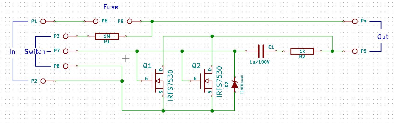
Actually, while I figure out the details of a push-to-start antispark, here’s a relatively simple lowside antispark switch that implements pre-charge. I have a prototype of it at home, but won’t be able to post a picture of it until this weekend. I actually used said prototype in my mountainboard before I moved on to the LTC7004 switch.
If anyone wants to mass produce this and sell it for a low cost feel free.


https://easyeda.com/RuBisCO/LowsideSwitch
@Pedrodemio This design shouldn’t cost more than $10 to make per unit. Maybe $40 for three due to the shipping cost on the PCBs, but protoboard can get around that :P.
Yeah might be decent gadget to lump in with my FOCers
Thanks a lot
If @shaman does it I will probably get one if it can handle a good amount of current
My design still as it was since I’m having little time to work on it
How much current is considered a good amount?
I’m aiming for 100A peak I.e, for at least 30s, probably that’s already considered continuous
Sort of a tall order but not impossible. Just more FETs in parallel and maybe a small heatsink
Actually, I speced the wrong MOSFET, the price on the ipb014n06n went up. Better would be to use three TPW1R306PL,L1Q in parallel. I’ll redo the schematic and design to incorporate those mosfets instead.
ok, how does this look?


I see you are using “thermals” for connecting the FETs and OUT/BATT pads to the planes. While this makes soldering easier, you constrict current flow during operation. Maybe consider have direct connections with these pads for improved current flow and less heating during operation.
Also consider utilizing the bottom layer for helping carry the high current portions as well. You can via stitch the 2 layers together.
@shaman is exactly correct. Don’t use any thermals and use both sides of the PCB to carry current AND wick heat away from the FETs. I would also space the FETs as far from each other as possible to allow the centre one to get more heat out. I would also ditch through hole components.
I’d say the choice of through hole vs smd would be whether or not you want this to be easy to assemble by a DIYer. SMD would better for Design For Manufacturing (DFM) since pick-and-place is low-cost compared to manual soldering. Pros and cons to each choice here
I agree with the general point about diy, however I think for this application it doesn’t make sense for 3 reasons.
Hi @Gamer43, along with my other comments. I would make all the traces on this board much thicker. This board is safety critical and will be in a high vibration environment. Last thing you want is a trace breaking.
The MOSFETs have leads on them, they can easily be hand soldered. I know because I did it on a flipsky 4.20 xD.
(yes aside from the faults common to all pre-fix 4.20’s, it works just as it should :P)
If the plane thermals are removed, those mosfets will not be easy to solder. Easy for me, easy for you sure. However if someone is in the situation where they think that 0805 ish surface mount is too hard, they are going to struggle with mosfets attached to large copper planes.
To me it makes no sense to have a board where you are saying that surface mount resistors are too hard, need to go through hole. However soldering a large mosfet to a solid copper plane with a center thermal pad is easy.
It is when you use the TS80 soldering iron :PPPPP
Seriously, that iron rocks at heat delivery. Dave from EEVblog soldered a TO-220’s tab to a huge copper ground plane with it.
Edit: here’s a picture of the prototype.


MOSFETs used are the IPP029N06N