I don’t think there is a problem operating in the linear region as long as you design the circuit correctly to not exceed the maximum ratings for the FET. Every product I have designed that uses a FET to switch power simply ramps the FET slowly enough to not exceed ratings. Don’t use 555 timers, they will make the problem worse, just use a resistor and capacitor on the gate and get the values right to not exceed the current rating of the FET.
Quickest way is to just do a spice simulation. Let me know if you need help with this.
Nice, would gladly accept some help, I have an idea how to do it but trust more in someone else
The LTC7004 datasheet has some formulas to calculate the rise time but I doesn’t take the current into account
On the spice we would just put a transistor being turned on by an RC network while powering a capacitance equal or greater than both VESC’s combined and watching how high the current gets?
My only suggestion for whole this project is not to put mosfet into linear mode they burn instantly doesn’t matter how many 2,3,4 you will put in parallel inrush currents are thousands of amps for few tens of ms you can check your mosfet SOA and will see that these inrush will kill it instantly.
That part I understood, but wouldn’t the soft turn on of the LTC7004 with an adequate rise time make the current low enough? Or since an empty capacitor is almost a short, no matter how long the ramp up is the current would still be big?
There should be formulas for calculating inrush current, if not, assuming you know the rise time, the inrush current will be (Load Capacitance * System Voltage ) / Rise-Time.
For example, system voltage of 40V, load capacitance of 3,000uF, Rise-Time of 100ms, inrush current will be
3,000uF * 40V / 100ms = 1.2A.
The purpose of the RC timing circuit is to limit this inrush current from the hundreds of Amperes to something more manageable such as a couple amperes or even less than an ampere. In this case, since the rise time is significant, the circuit just needs to not exceed the maximum power dissipation of the MOSFET, which in this case is 170W.
From the above example, the peak power dissipation will be 50W (40V * 1.2A).
It has a very low quiescent current, less than 1mA, something like the ZXTR2112F-7 provides a 12V supply without issue.
In order to implement automatic turnoff, bi-directional current sensing and some kind of timing element is required. This is most easily realized with a current sense amp and a microcontroller. It can be done using a current sense amp and window comparator with timing circuit, but that is really annoying to design.
Unfortunately all of the LTC700x series chips with current sensing only have unidirectional current sensing, not sure how it would behave with negative load current.
But, if the on-chip current sense amplifier recovers without a problem from negative saturation, then using the LTC7003 in tandem with a MCU can implement automatic turnoff.
I have not worked with such high power circuits before, but I have destroyed my fair share of power MOSFETs (mainly from avalanche breakdown), and I have destroyed power MOSFETs in a low side switch which did not implement precharge.
I currently have two switches designed with the LTC7004 working in an electric mountainboard and electric scooter for a few months now, they switch 40V with a load capacitance of 1,200uF - 2,000uF.
I have tested them up to 42V at a load capacitance of up to 6,000uF.
They have a rise-time of 100ms (might be longer because I didn’t size my capacitors correctly) and use two IPB014N06NATMA1.
If they fail next week, then you have proven your point.
There is a load capacitance at which the switches will fail, but that’s why designs have to keep things like those in mind, what is the highest load capacitance and system voltage this device will encounter and can it survive in those conditions?
In this case, longer rise-times will be required to handle large load capacitances and supply voltages.
The RC timing circuit as described in the LTC7004 datasheet FORCES the gate voltage (referenced to ground of the system!) of the MOSFETs to rise linearly, and the source voltage trails by 2-4V (voltage at which miller region is encountered). The MOSFET is driven in the miller (linear) region, it passes the necessary current through it to have the source voltage rise at the same rate the RC timing network charges.
Because of the way capacitors work, in order for the voltage across them to rise linearly, a constant current must be passed through them.
Basically the MOSFET is being driven to act as a constant current source until the load capacitance is charged to supply voltage, and because of the way the miller region works, the rate of voltage rise ends up being linear.
This is exactly what happened in Blasto’s LTSpice simulation.
Constant current through MOSFET (at non-constant drain-source voltage) and linearly decreasing drain-source voltage.
The issue with low side switching is since everything is referenced to ground, it runs the risk of accidentally shorting something to ground, the device being switched ends up floating at some significant voltage above ground.
@Pedrodemio
Hey guys, I drew up a schematic that I think should work for an antispark switch to implement push-to-start and automatic turn off (not sure how accurate the embedded current sense amp in the ltc7003 is, so not sure if auto turn off is viable with the ltc7003, if not, would have to leave the current sense feature unused and add an ina240 current sense amp, Push-to-start may not work with extremely high kv motors or high speed gearing, in this design, it relies on the BEMF generated and rectified through the motor controllers).
It would be used with a momentary push button such as this https://www.adafruit.com/product/481.
Let me know what you guys think, if this looks viable I’ll see if I have time to build and test a few prototypes.
Drawing up a BOM, using parts from Digikey, and using JLPCB’s quoting tool, for a prototype run of 10 of these, 2layer 2oz copper, the price would be $20 each to produce.
Would be slightly cheaper (~$17 per unit) if ordering from Arrow.com.
Actually, while I figure out the details of a push-to-start antispark, here’s a relatively simple lowside antispark switch that implements pre-charge. I have a prototype of it at home, but won’t be able to post a picture of it until this weekend.
I actually used said prototype in my mountainboard before I moved on to the LTC7004 switch.
If anyone wants to mass produce this and sell it for a low cost feel free.
@Pedrodemio
This design shouldn’t cost more than $10 to make per unit. Maybe $40 for three due to the shipping cost on the PCBs, but protoboard can get around that :P.


 You know better and u have design and replaced design n times
  sot block mosfets burn which are rated 4kA impulse currents
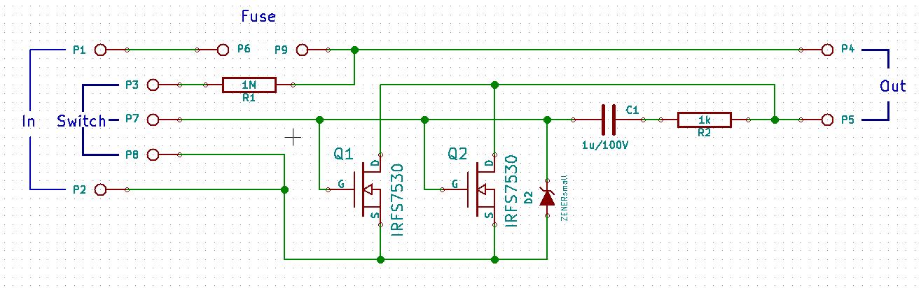
 Hey guys, I drew up a schematic that I think should work for an antispark switch to implement push-to-start and automatic turn off (not sure how accurate the embedded current sense amp in the ltc7003 is, so not sure if auto turn off is viable with the ltc7003, if not, would have to leave the current sense feature unused and add an ina240 current sense amp, Push-to-start may not work with extremely high kv motors or high speed gearing, in this design, it relies on the BEMF generated and rectified through the motor controllers).
