Funny is, a lot of these are in the wild. I mean a LOT. But I see one or two builds. Then I gathered if people do not talk about them, that’s a good thing, most of the time people start talking and looking for solutions when something does not work or have overall bad experience. Sadly all the good comments and thanks I get by email so no point in sharing as it might seem fake
1 Like
Another thing I wanted to share is I am engineering some stuff for the printer. The major thing is automation. I have two inexpensive ideas to try. One is nearing test phase with conveyor part removal. This allows unlimited parts to me manufactured unattended autonomously.
Here is most recent photo
 Another approach is using al2o3 porous ceramic plate with vacuum to hold parts while printing and then push them from build surface with lever. I am skeptical about this one as surface at the start of a print is very small for vacuum to work vut you never know. Needs to be tested.
If any of the solution will work, I will be able to cut my prices by further 10%.
Another approach is using al2o3 porous ceramic plate with vacuum to hold parts while printing and then push them from build surface with lever. I am skeptical about this one as surface at the start of a print is very small for vacuum to work vut you never know. Needs to be tested.
If any of the solution will work, I will be able to cut my prices by further 10%.
7 Likes
Well then one idea would be to encourage them(people saying thank you) to share a pic of their setup(on this thread or email them to you) and then you can put those pics here or on your web page, with their permission of course. You should def do that. Make different categories for their application and post pics under them.
Conveyor seems to be the easiest to implement. Also i am skeptical about the vacuum because it won’t let the bed heat up. Are you going to use tool steel plate for the conveyor, that is fed through certain distance using a servo?
If vacuum holds, then there is no need for heat, after all heat is used to get prints to stick. Conveyor will have a belt on top of aluminium heated platform. After print is finished, stepper motor will turn the conveyor and drop the part into collection bin. The another part will start and so on. I have 0.05mm stainless scheet to test as well as 0.25mm single layer carbon.

3 Likes
Have you seen the endless Y axis design? It uses a rolling bed very innovative Edit: you have indeed!
Any chance that you would look into cell level fusing at some stage? A mod to the case design and the cutting of tabs is all that is required.
Also/or some balance wire conduit/passage where they are safe from a short. That’s nice work with the Fomula E car, this is useful to the above ^
1 Like
Yes, the blackbelt. Its good for long parts but smaller does not look too good when printed. I have not seen such printer producing same quality parts as conventional printers and you are constrained how you orient parts. You get away with some overhangs but there is the other side to it.
1 Like
the moment i read conveyor belt i thought “Factorio”. Congrats on the cooperation with Formula E. Great stuff, love the new lower profile.
@agniusm, can this is printed without support? What settings do you recommend. I realize it varies between different printer setup but it will give me an idea.
Sorry but what? If you are talking about NESE, they are designed to be printed without supports as is
My question was about your slim file.
Sorry but no. I have not changed my mind on this. Having read formula e rules, there is no requirement and their regulations are strict. Its a complexity over nothing. I see why you would want that on second life cell in your house.
Its possible. You can make the nipple as wide as the cell, add proper fr4 gasket to positive of the cell and drill out the nipple so it sits on cell positive side negative edge. Than just solder or weld your fuse wire.
OK, if you dont mind soldering, can assemble 10k of orders, i can do it, and it will cost same as the usual tab 
2 Likes
No supports on that too
I’ll pass thanks 
But good option for diy so always worthwhile meshing ideas
You are not determined at all mate  For diy, yes. You can do it even with existing tabs i think. Just need to find a round gasket to cover up positive terminal. Drill a hole on the tab nipple and solder your fuses inside the nipple and to the cell. Inserting it might be tricky
2 Likes
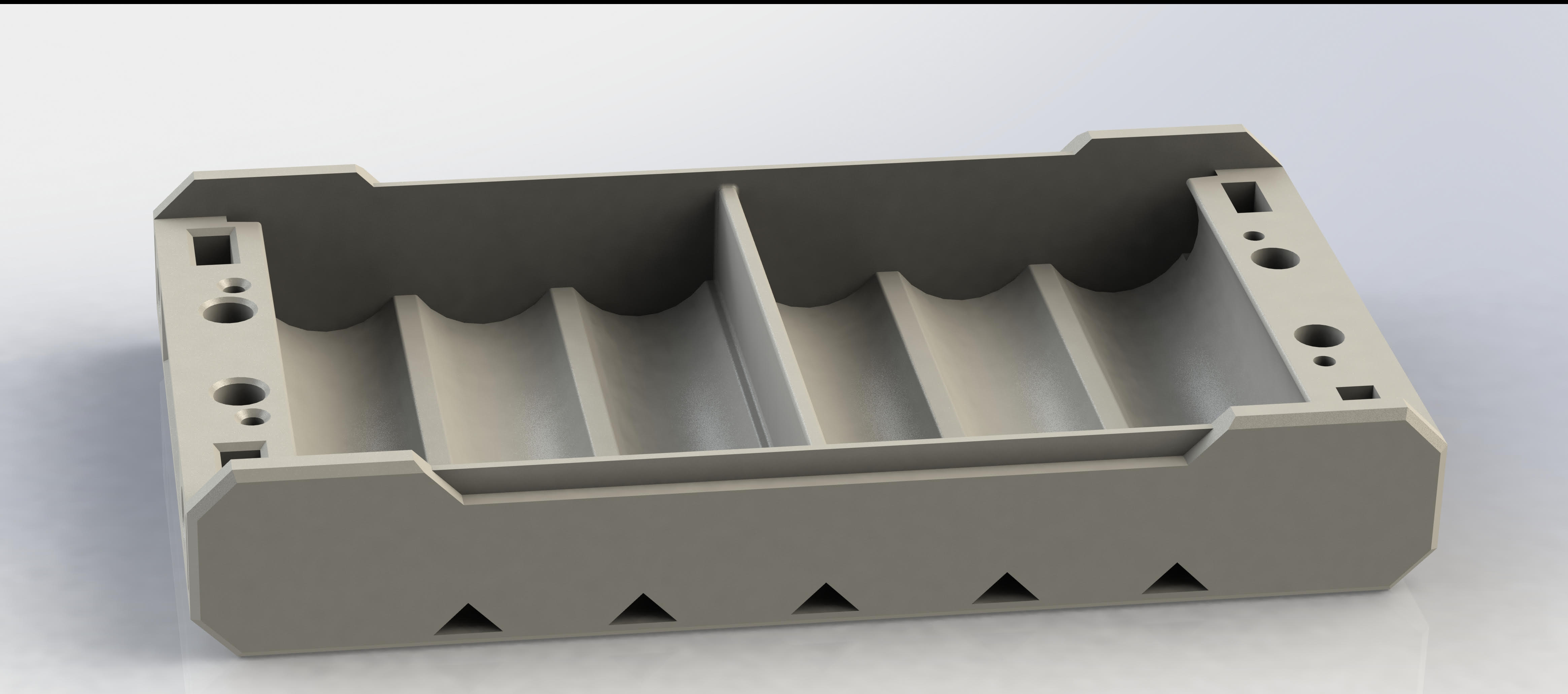
Hey @agniusm, I have raised this concern with you before, but still wanted to do it again for a sense of security. Since the new slim pack is specific to electric skateboarding, could you please put a divider in between? That will make sure that under no freak circumstances will the middle 2 cells come in contact with each other. Plus it will provide additional strength. A divider bar like in the pic below. Sure I have the cad and make the modification but this is for rest of the people.
Edit: this is only for 2S packs. Like 4P+4P
2 Likes
Do you mean from flexing? I would suppose the packs should not be under stress, I think you designed some holders for the packs with a flexible type design, surely the flex should go into that?
If the pack flexes and the cell wrap disintegrates the only risk I can see if that the negative cans touch each other…which they already do at the negative pole
The cells in the tray are all the same parallel group, not sure how a short occurs in the scenario painted?
EDIT: Ah right I get you using the 2p in a single pack, yes that could happen & your suggestion makes sense. You could easily chop and add that before Agnius gets around to it
That’s what I was thinking too, maybe we should add that it concerns the 2s packs only 
1 Like
The middle 2 cells are not from the same parallel group. I fear that say a crash happens and the impact makes the middle 2 cells touch each other momentarily. Then a short would happen producing a lot of heat and then melt the plastic leading to a full blown short.