Bottom screen is the SPI communication, I connected the oscilloscope to check if everything was working and how it looked. I discovered that upon the the first connection I swapped 2 wired, that error was easily found with the oscilloscope.
Testing encoder operation:
Comparing sensored with AS5047 to sensorless (no studdering as with HALL sensors):
Configuring the AS5047 encoder on the VESC with BLDC-tool:
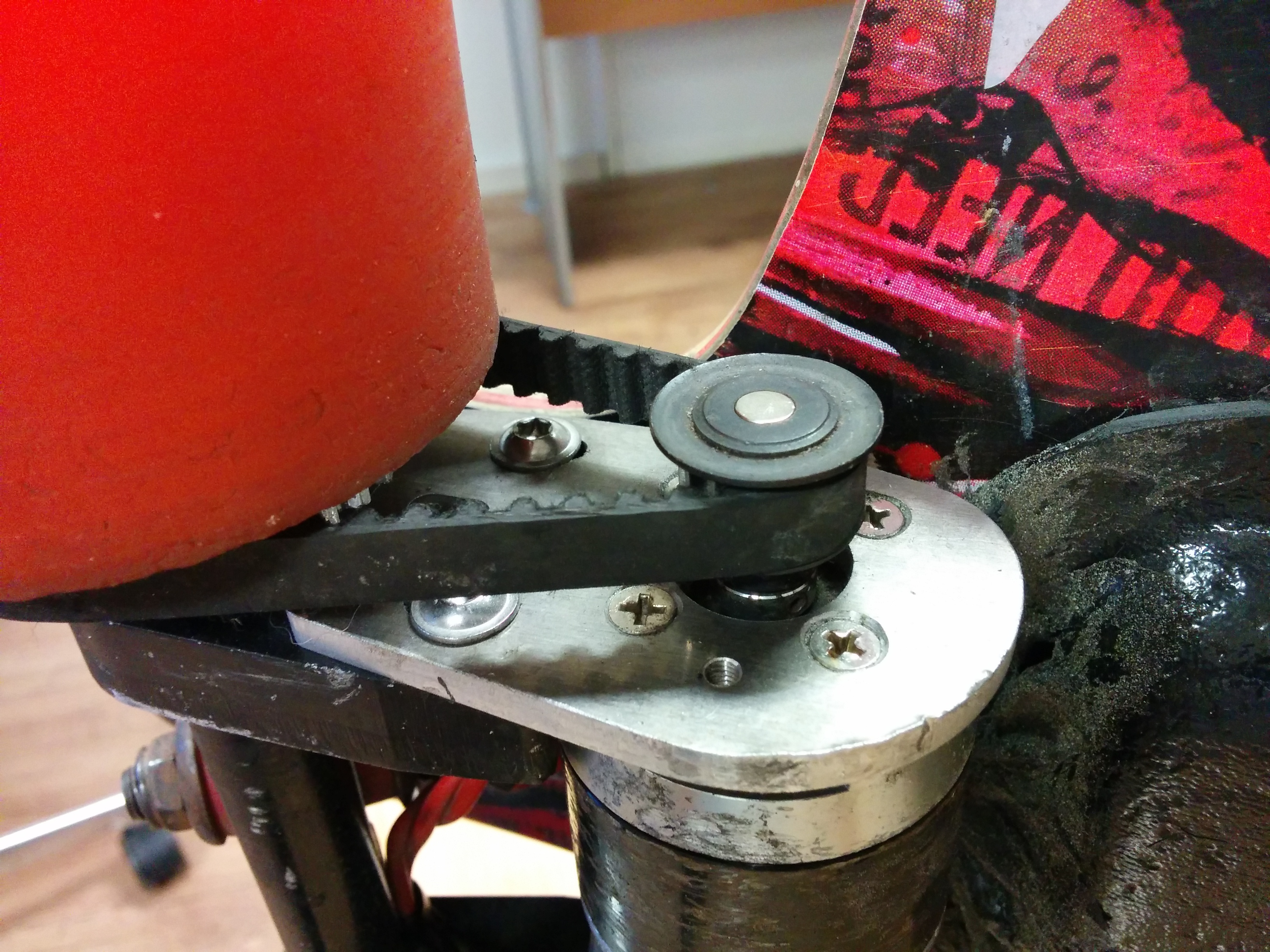
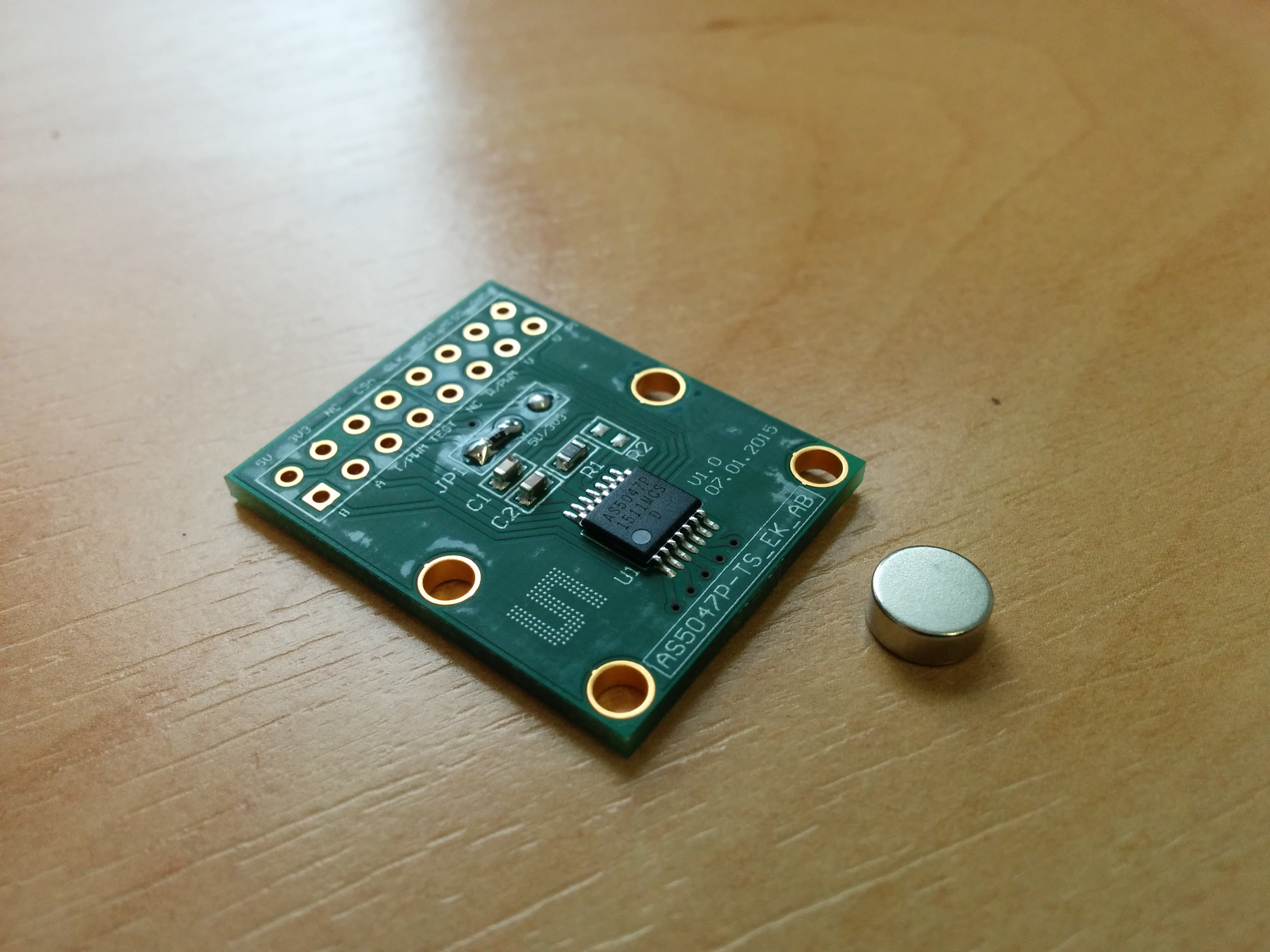
It is a development board for the AS5047 magnetic encoder chip. The chip tells the VESC the exact ( with 14bit accuracy ) rotor position, when the vesc knows this it has a far better way of applying the correct magnetic hield in the motor enabling perfect low speed (even at 0 speed ) torque control. I am now able to start very smoothly from standstill.
Yesterday we tested a setup with HALL sensors, while that was ALOT better than sensorles it still had some studdering at low RPM.
Great to see someone diving into the magnetic encoder support of the VESC. I have heard that the non linearity of the AS5047 leads to problems with higher RPMs. Can you confirm that? Comparing the hybrid mode (where the VESC uses the magnetic encoder for lower RPMs and then switch to sensorless mode for higher speeds) with the complete sensored mode should show that.
Isn’t it bad to stick the magnet directly into the steel pulley? I think that results into a different magnetic field which maybe decline the accuracy of the encoder.
Are you using a 6mm shaft (so a 6mm pulley) because the magnet used for the AS encoder have a 6mm diameter when I am not mistaken?
I think you don’t get it. The support is already implemented by Benjamin Vedder. So you will see the code in his github.
@JTAG just build the supported hardware in his board.
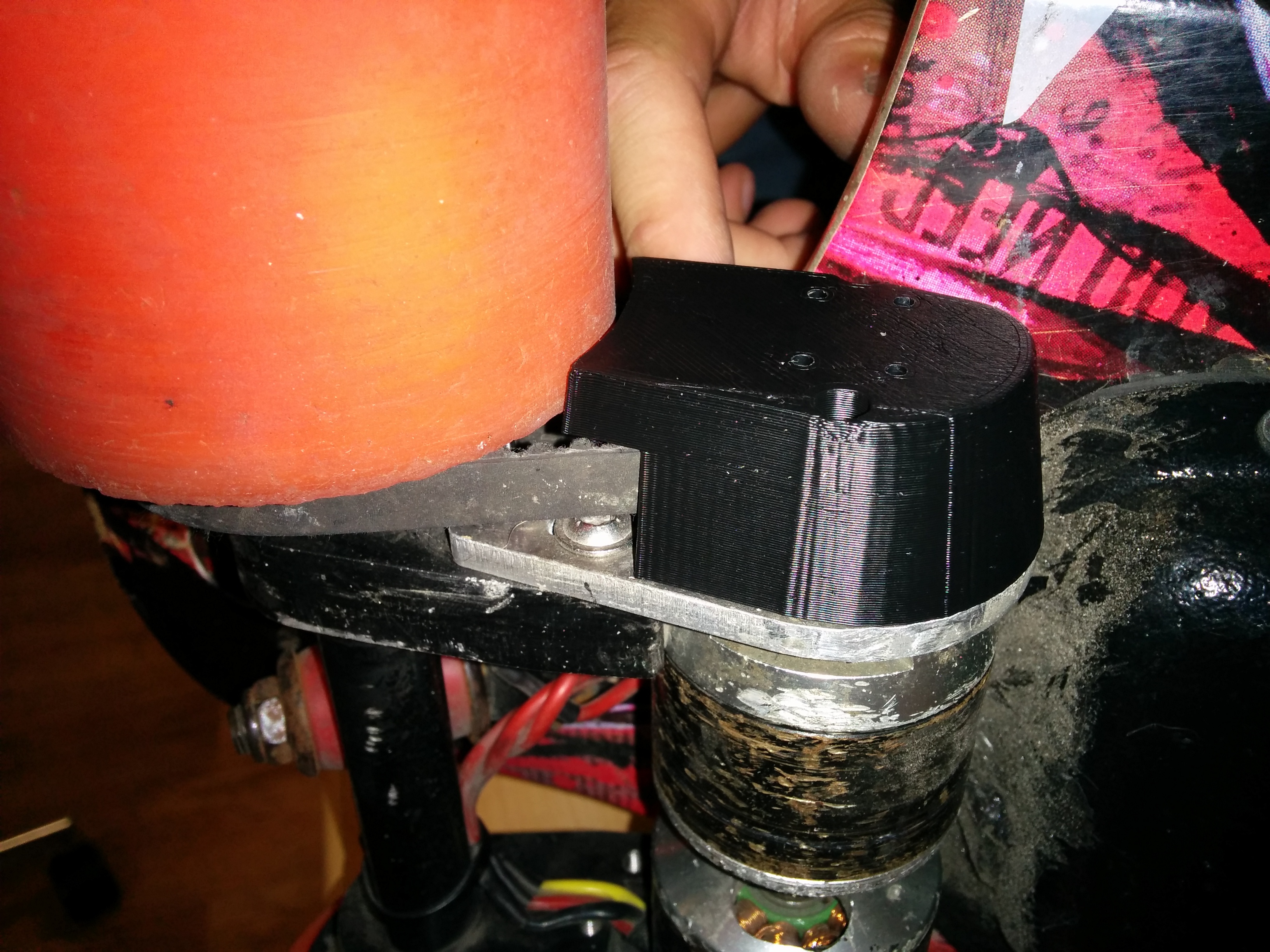
Yes it was benjammins work implementing the encoder. I was to lazy to design and build a PCB that fitted my exact needs so I just ordered the development boards since they were so cheap. It was surprisingly easy to make really, most of the effort went into designing the 3D model and printing it (and that was the contribution of @MrEpiquad ^^ ).
@hexakopter
Non linearity in what sense? I havent noticed anything bad, the board is now so much more fun starting from standstill. Low/zero speed is the only reason to use an encoder since at higher speed the observer does a much better job of determine the rotor flux angle.
Yes for sure the metal pully will bent/guide the magnetic field making it less ideal. I think this will result in a bit more noise on the encoder output, but hey we have 14 bits to spare xD. Yeah the magnet is 6mm and coincidentally the motor shaft is as well.
Yes, remove the filters like you would when using an encoder. I noticed that when using cables that have their wires right next to each other without separate shielding (like USB cables) a series resistor of 47R instead of 0R is needed to prevent cross talk (needed for the chip select and clock signal ).
Hi JTAG,
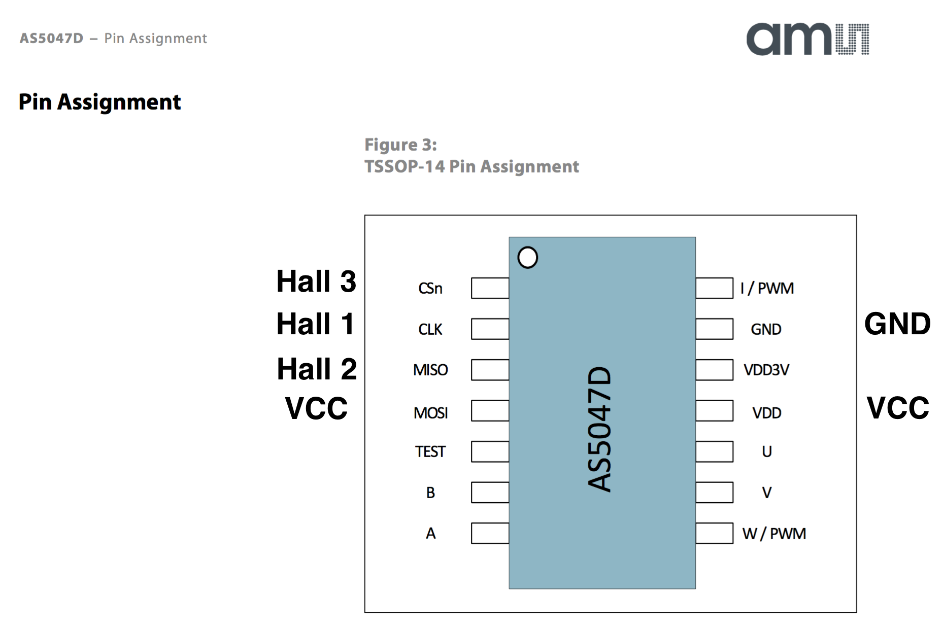
I removed R11, R12, R13, C5, C6, C7 and replaced R8, R9, R10 by 0 Ohm resistors. Unfortunately it does not work yet, therefore the question: Is the wiring as indicated in this Image correct? Might this be a problem of Cross Talk?
Hmmm, everything looks OK. Did you change te sensor mode to AS5047 in the bldc tool? Cross talk is a serious problem indeed with these high speed SPI line. Also take special care in the alignment of the magnet (de datasheet / reference design manual tells the criteria).
Any easy way to verify the basic functionality is to measure on the AB (or I) output, a toggling signal should be visible when the magnet rotates.
You probably know this already, just to state the obvious: the type of magnet used has a specific north / south pole orientation, please make sure yours has something similar.
Hi there,
First off, let me say that i’m very impressed with the work that you’ve done here. So, after you’ve modified the VESC by essentially removing the filter and switching the resistors to around 0 ohms, what part of the code did you have to modify to allow the encoder to be recognized by the VESC? Any help will be much appreciated!
Hi,
So just to confirm, I would simply select the encoder from the BLDC tool without uploading any files onto the VESC? This will then allow me to detect the encoder without any firmware changes?
Maybe the question is better preserved here. Did you used the Encoders on all the kilometer driven with the board? On your other thread it looks like you are driving a lot and I am interested what your long term opinion about encoders is. Do you had any problems? Would be glad to hear about that topic.
Hi, and my apologies, I should have replied. Unfortunately no. the cable between de encoder and the VESC broke within about 100 kilometers or so, I never found the motivation to fix it. Although the response and feel of control is way way better I don’t really need them.