if you only face 5 pins it’s fairly simple. black is ground, red is 5v and the rest are hall sensors
2 Likes


Hi everyone, I just recently purchased a vesc from mboards and a torque boards 6355 260 kv motor. I was able to make an adapter to connect the bullet connectors but I am unsure how to wire the jst connector to my vesc since it is too small. The connector on my motor is a 6 pin.


I was wondering if I need to by a different connector and solder it to the motor wires so that it fits with the VESC.
Get 2mm jst plugs and pins. Cut the wires, crimp new pins and plug it in. Ready to go. If your sensor cables to short than just solder some 2mm jst extension on and good
Are these the 2mm jst connectors you are talking about? https://www.amazon.com/2-Pin-JST-XH-Balance-Connector-Adapter/dp/B00R1J91JY
Or is it these 6 pin 2mm jst connectors.
https://www.amazon.com/2-0MM-Female-Single-Connector-Wires/dp/B01IZWYK7I
1 Like
If you don’t want to make anything you can get some of them
If no than you need that one you choose but with 6pins not with 2
Looks good
ahh I see thank you for your help. Is there any certain order I need to connect them in because the vesc didn’t have any sort of instruction
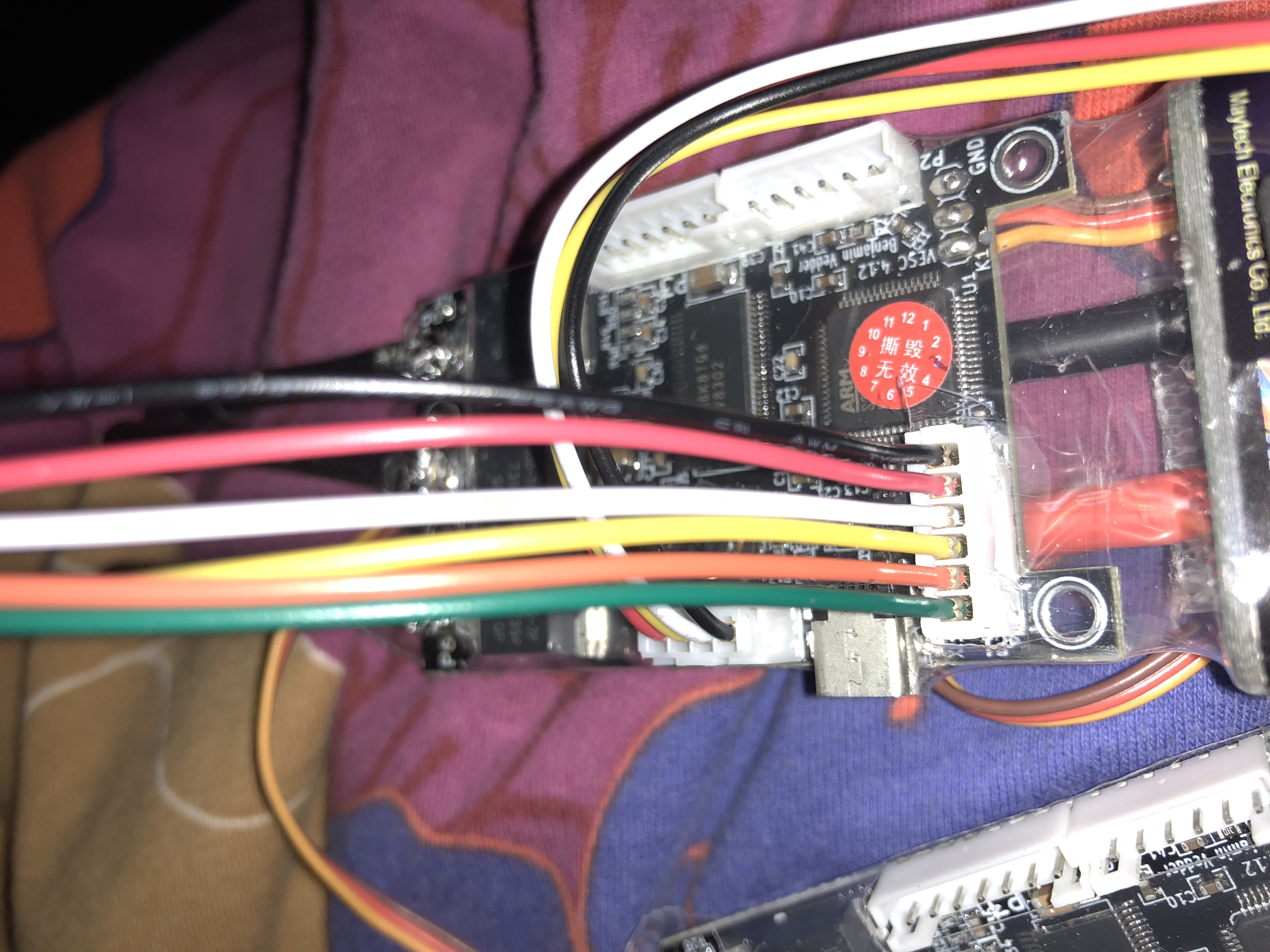
On the back side of your vesc there should be written which pin is what. Don’t mix + and - (red and black or better to say first and last pin) Sensor wires don’t mind which place they are
on the backside I see a 5v temp h1 h2 h3 and a gnd pin
1 Like
Normally you would get a adopter with it,if there is none,like I did buy a bigger jst connector and weld the wires 


1 Like
That’s it. Red is 5V black is ground.
1 Like
alright thanks andy, and so I just need to get the positive and negative in the right spot and the rest don’t matter where they connect correct?
That‘s correct! The sensors itself can be on any position on the plug as long as it’s not the plus or the ground.
To be not confused, the cable color from your torque board motors should have the right order already. The red 5V the black is ground.
If you have any other issues just let us know 
1 Like
@Jinra Hi i have the same problem @Redfire1 had in that my sensor wire on my motor only has 5 pins and my vesc needs 6. How exactlt do i plug it into the vesc?
On the Vesc look on the other side it should say 5v+, GN- ,temp hall etc,you don’t need the temp connection,try get a wiring diagram for you motor find the +and - and connect them the rest don’t really matter how you connect them,that’s what I did and it work.
I had the same problem with the motor having 5pin and vesc has 6pin I took your advice and left the temp/white wire out but now I have no reactions with motors which I previously did with original motors and I definitely didn’t let any white smoke out. I’m pretty good with electronics considering I have built 20+ drones. Is there a way to bypass the temp wire to make things work? I have been scowering the interwebs with no luck please help. Board is the inboard m1 with complete rear truck assembly from miles duel carbon shorty