Long story short. Started seeing a few Evolve’s around, even rode past a few on my bike, looked like fun. Begun investigating what other options were around and must have stumbled across this forum. Thought about it a bit and figured building a board would be half the fun, so why buy something off the shelf.
Anyway some of the bits are starting to come in so may as well start a build thread. Still haven’t ordered everything, in fact I’m still undecided on most components. I did a few semesters worth of electronics back in university, but that’s going back some time now… If it looks like I’m about to screw something up, it’d be great to know about it beforehand .
Arrived home tonight to find a box of batteries waiting for me.
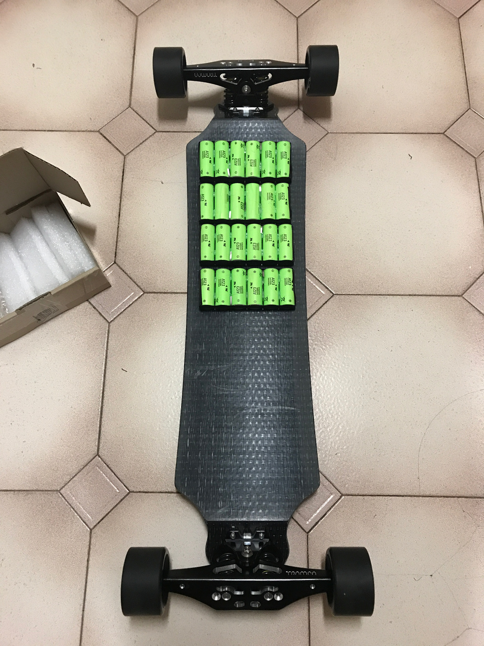
That’s 24 A123 26650 batteries welded up in a 12s2p configuration by Marsen (Aus). Really didn’t want to buy a spot welder, so was pretty happy to find they offered a pack assembly service. Voltage for each cell group checks out at 3.3v, which is probably a good charge level for them to sit at while I get everything else together.
There’s a 2mm gap between each cell, while this is probably good from a cooling perspective it means I have a little less space to work with across the board. Might look at removing the hot glue and closing up these gaps .
Six months later and it’s kind of looking like an electric skateboard .
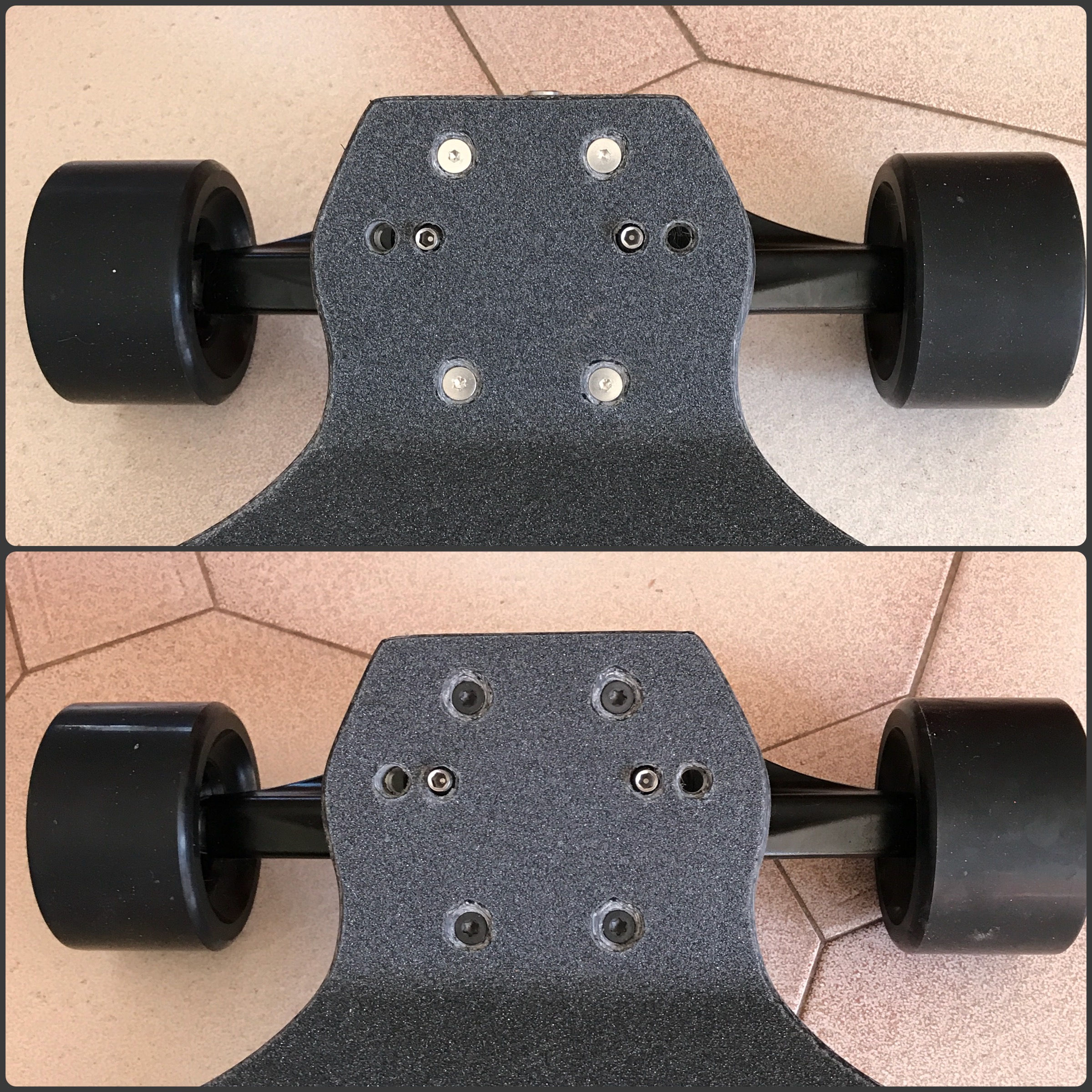
Bolted the drive system together just to see if everything fit. Need to pull it all apart again so if it looks like something is way out of alignment, it probably is.
For whatever reason my Trampa didn’t come with any of the little spacers for the axles, as a result the slave pulleys tighten into the mount. I’ll rig up something. I didn’t get a ‘Trampa’ sticker for that matter either😭.
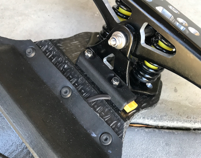
Circlip on the 10m APS shaft is uncomfortably close to the mount. Will grind down the two little loops you’d use to open it. Just need another 0.5mm clearance.
The ‘collar’ on the 10mm bore motor pulley is too thick for the gap in the motor mount. I could leave this flipped (as shown above), but will probably find some creative way to machine it down without a lathe. Would Like to run some larger wheels later on, so I’d prefer not to have this sticking out.
Excluding the BMS, which is on its way from Rome now, I think I’ve finally got all the bits needed to finish this thing off.
The inner mould is really designed around my a123 26650 12s2p battery pack, so I’m not sure if it’d be much use to anyone else. The battery segments are each 30mm deep, you could fit one row of 18650’s, but not two, and then you’d be limited to a 8s4p setup .
Would like to see Trampa work on its options here. Not a fan of the cut up Trampa battery tray, or the battery boxes they mount over the rear wheels. Functionally I’m sure both are fine, just the aesthetics (and having to cut that Trampa material), but it’s pretty subjective so…
Nice build, loved this new aproach to making and enclosure
Did you end up reinforcing the connection of the cell with a cooper wire? I highly recommend, theses batteries can deliver a ton of current, even more since you are using 2P, but if you try with these 2 nickel tabs I can almost guarantee that something will melt
According to a topic in endless sphere, each 7mm nickel can handle 10A getting a little bit warm, so for your battery 20A, these cells can supply 100A, if not more
The nickel is bowel upward as I needed to reduce the space between each cell otherwise each row of 6 was too wide for the deck (these came welded together). Tempted to pull the whole thing apart and solder the 10awg wire directly to each cell.
FWIW I’ll be running a 70amp fuse, and will be setting each vesc to pull 30a or less (that’s still 30a per cell!). First esk8, I really don’t need it to be fast right now. The risk is I get comfortable on it, and start wanting to push the power limit later on.
I see, it’s better than the original for sure, what I usually do is to strip que insulation completely, this way you have more contact area, it could help in your case
The best test you can do is ride it hard and put you finger on the connection, if it’s not burning hot it’s probably ok
Also by the looks of it is seems that you need a more power when soldering to evenly distribute the tin
Agreed, although this wasn’t the final state (added more solder/balance wires). My soldering iron heats up to 480degC but still seems to lack outright power and thermal mass to do these big wires well.
I’ve got four 100w resistors I’ll rig up into a circuit to test this initially. For this pack (approx 40v) they’ll only be able to dissipate 10a max though, hardly a thorough test. Still looking out for other ways to bench test.
Try a hair dryer, most of them work fine in DC, you may need to parallel more than one to get the power a lower voltage. Or use a shower heating element. Unwind the nichorme wire and a cut it were you have the appropriated resistance, if it burns out out it in the air you may need to throw in the water
But the looks of it… an instant boner! Best of ALL designs for a Trampa enclosure out there, srsly! Love it to bits! Mindbogglingly meticulous job! And ima also not a big fan of the indigenous Trampa option for it - I’d go for yours should it be commercially available and with other cell capacity options. LOVE IT!
So I did a few battery pack load tests; results can be found over in the other thread. Everything checks out ok up to a 6a continuous drain, which admittedly isn’t high.
Now for the big news… well for me anyway. For the last 7 months or so it’s just been an inanimate object sitting in the corner. Last weekend I finally plugged it all up and got the motors spinning.
Amazingly it even worked first time; FOC, hall sensors, all checked out. The only issue being I had the VESC plugged into channel 1 on the receiver when it should have been 2; that was a anxious minute or two . One of the VESCs seem a little bit temperamental as to whether it will connect to the VESC Tool or not; often requires restarting the VESC Tool/VESC itself and or plugging in/ unplugging the USB. Couldn’t find a reliable process, but was never unable to connect given enough messing about.
VESC Tool itself was really quite nice. Stepped through the wizards and had everything going in minutes.
Just waiting on a few parts from Shapeways so I can tidy things up and bolt it all together.
Shapeways order came in. They had the print done inside a week, but it took UPS 3 weeks to ship it down here. Took the day off work yesterday to try and get this finished up.
All the CAD/STLs can be found in my GitHub repo. They’re all pretty specific to my build, but I’m happy for anyone to do what they want with them.
Mount for the display and power button. Figured that in future the power button may be used to do more than simply switch the board on and off, hence why I wanted both the display and power button close. Packaging becomes an issue which is why both the display and button are angled like the are. Besides this angle makes it more perpendicular to your eye when standing on it.
The top of the button is recessed into the mount, and the button itself needs to be pressed in 3mm or so. Furthermore you need to hold down the power button for a few seconds to turn the DieBieMS off. I’m not particularly worried about accidentally turning it off with my foot.
Gets pretty busy back there. Had to drill a 13mm hole through the deck as the power button extends below the surface a bit. This was one of 3 designs, first would have required digging out too much of the deck, and I didn’t like the mount hole locations in the other (although it did integrate the charge port).
Pretty happy with how the charge plug worked out, despite spending very little time on it’s design.
Spent like 10hours or so yesterday finishing everything up, it was quite the PITA getting all the cables connected and routed out the back. Anyway, think it’s finished now. . . well as finished as these things get. Writing up this post to kill some time for the Loctite to cure, wheels spin but it’s not been ridden yet.
Just on testing safty gear Ive com off at 18mph 25mph and 32mph all when i was testing do a few miles 10mph and then 15mph do a strip down check wires build up from there
Yeah, that’s what I was thinking, going to roll around pretty easy for a while. VESCs are set at 20a (batt max), and there’s a BT module I want squeeze in too, so I’ve got other reasons to open it up in a little while.
 .
.
 .
.

 .
.


 .
.

 Best of ALL designs for a Trampa enclosure out there, srsly! Love it to bits! Mindbogglingly meticulous job! And ima also not a big fan of the indigenous Trampa option for it - I’d go for yours should it be commercially available and with other cell capacity options. LOVE IT!
 . One of the VESCs seem a little bit temperamental as to whether it will connect to the VESC Tool or not; often requires restarting the VESC Tool/VESC itself and or plugging in/ unplugging the USB. Couldn’t find a reliable process, but was never unable to connect given enough messing about.


 Where are you mounting the bms?