i like the external BMS. thought about building my own charger like this build has. its hard to find external chargers that are 10 to 12s. lots of people do two 6s banks for charging.
Really loving this thread. Nothing to add, just watching and learning 
This is great. I want to do something very similar for my board. I also already installed the same 12pin connector.
Why the DieBieMS? That seems like overkill, especially since you already have a solution for monitoring individual cell voltages and even for manually balancing with the bleed resistors. That alone is already good enough. Overcharge alarm can be configured on BS12, so you would be notified that you should disconnect the charger. Seems like you need no BMS at all. If you do want extra protection, any cheap bypassed BMS would do.
@dareno is this the one you ment? About bms integrated charger?
@SkaterBoy58 I think you should start a separate theard on this charge once you get more into it. Abosolutly love the idea.
Thats the one. Looks like a cracking idea.
1 Like
OK
Will start a new thread for my external BMS/Charger see https://www.electric-skateboard.builders/t/external-bms-and-charging-box/79444
Cheers
1 Like
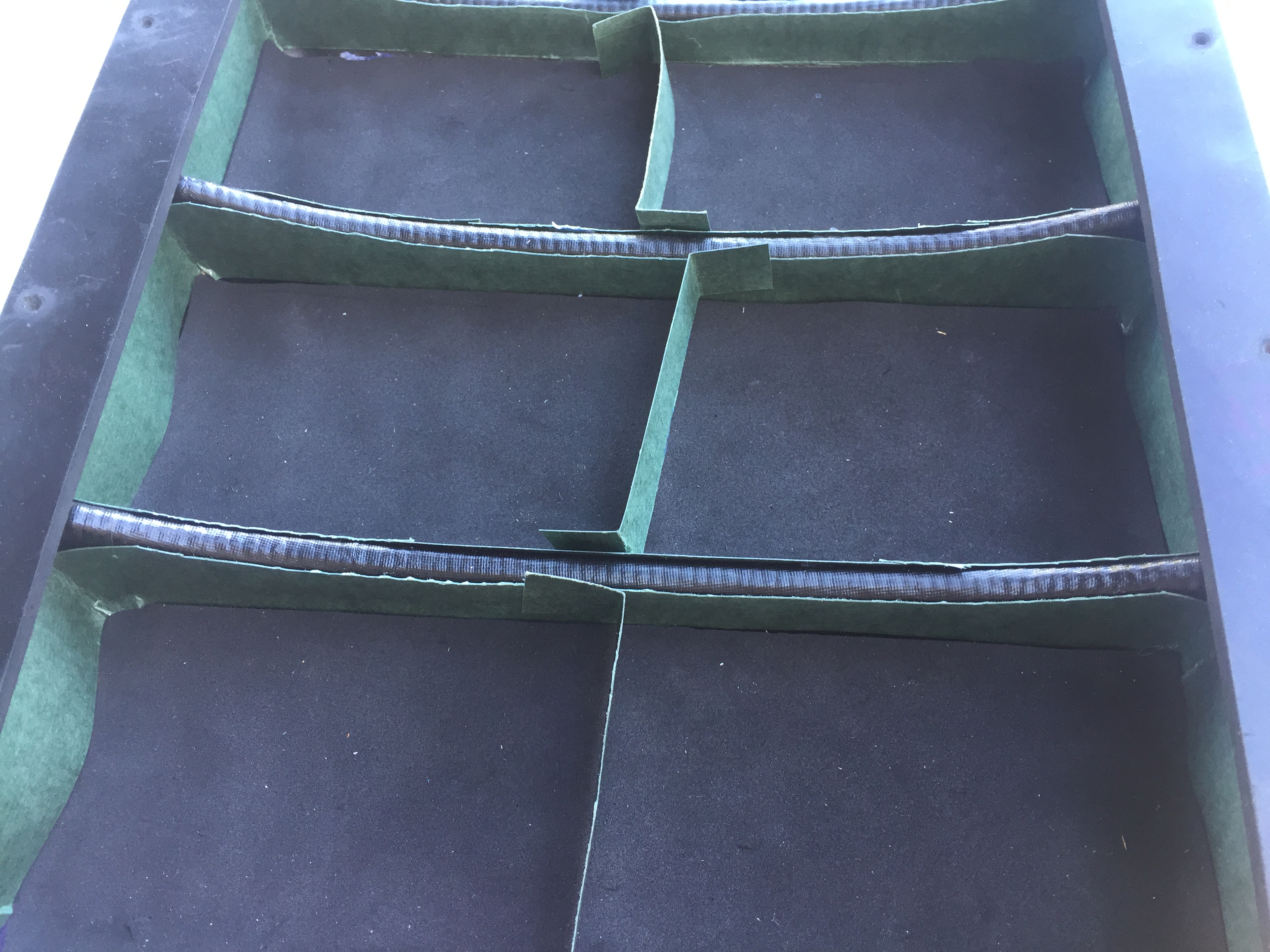
neoprene foam hot glued to bottom of compartments for battery cells to sit on and fish-paper cardboard hot glued to sides of compartments for insulation - with the middle strips to fit between cell packs
10 Likes
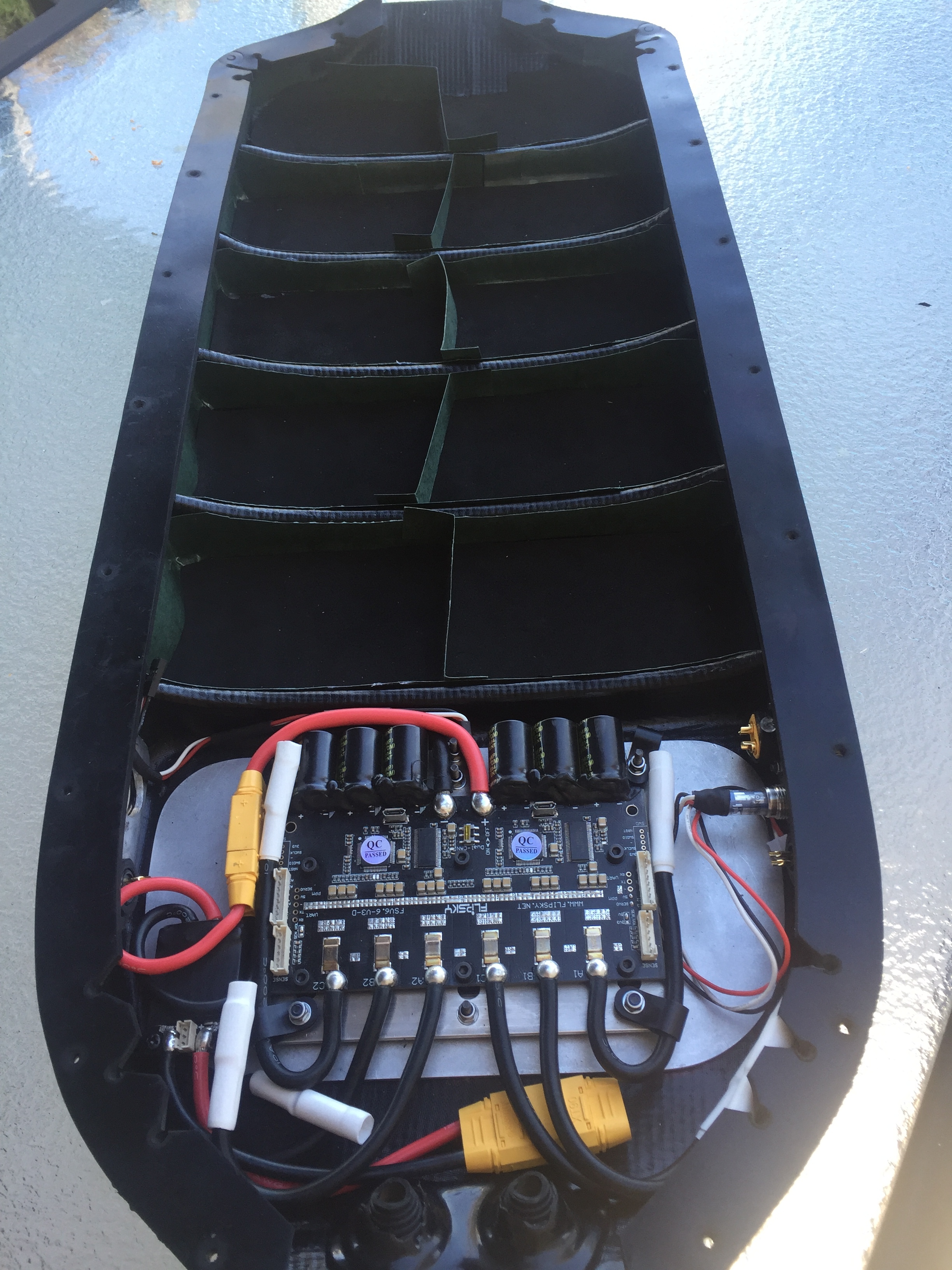
Completed building battery pack with all series connections and balance wires connected to enclosure socket.
Charged battery to 4.15V per pack using DieBieMS BMS (with cell misbalance set to 5mV) and CC set to 0.5A for final charge above 41.0V. Total battery voltage was 41.5V
Next step is to complete a battery discharge to confirm battery Ah and Wh capacity and to confirm that all cell packs discharge uniformly.
The load for this test is my trusty old 8-ohm 100W wire wound resistor mounted on a fan that I have used for discharge testing of previous battery builds. This provides approx. 4A current.

The Samsung 50E 217000 cells are advertised as 4,900 mAh minimum with nominal capacity of 5,000 mAh. These stated mAh capacities are for full discharge from 4.2V to 2.5V.
I have 10 x 6P packs of these cells so am expecting approx. 27Ah battery capacity for this discharge test from 41.5V and stopping at 3V with a Wh capacity of approx. 975 Wh.
The discharge test should take about 7 hours.
Measurements of discharge current and all cell pack voltages (using real-time data on DieBieMS Tool) were taken every 15 minutes for the first hour and then every 30 minutes after that.
The Ah was calculated over every time interval using the average current over the interval multiplied by the minutes – and then accumulated for duration of discharge test.
The Wh was calculated over every time interval by multiplying the time interval average current by the time interval average voltage (sum of all 10 cell pack voltages) multiplied by the minutes – and then accumulated for duration of discharge test.
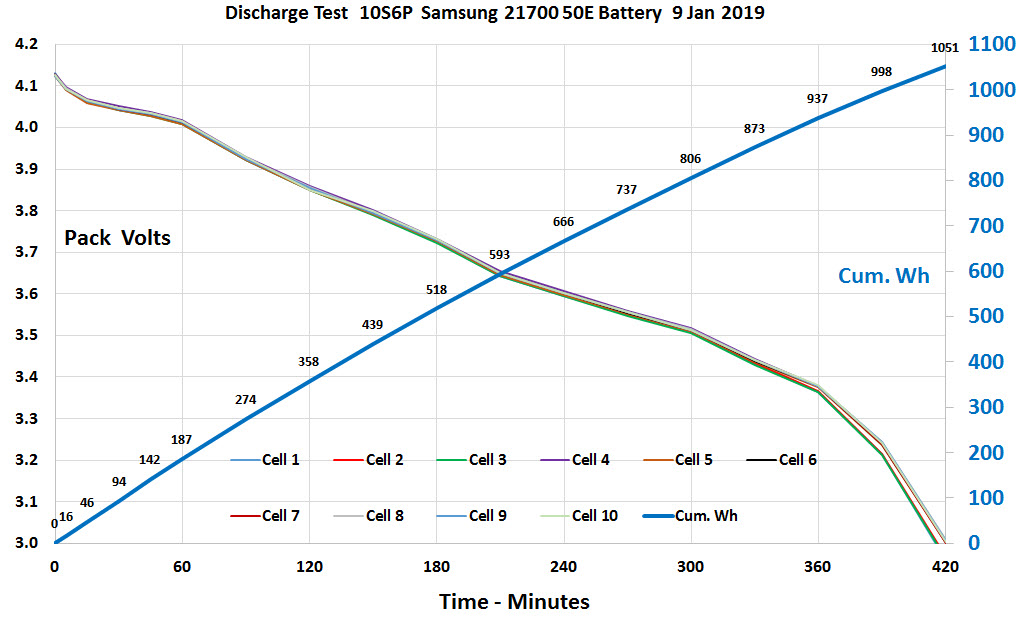
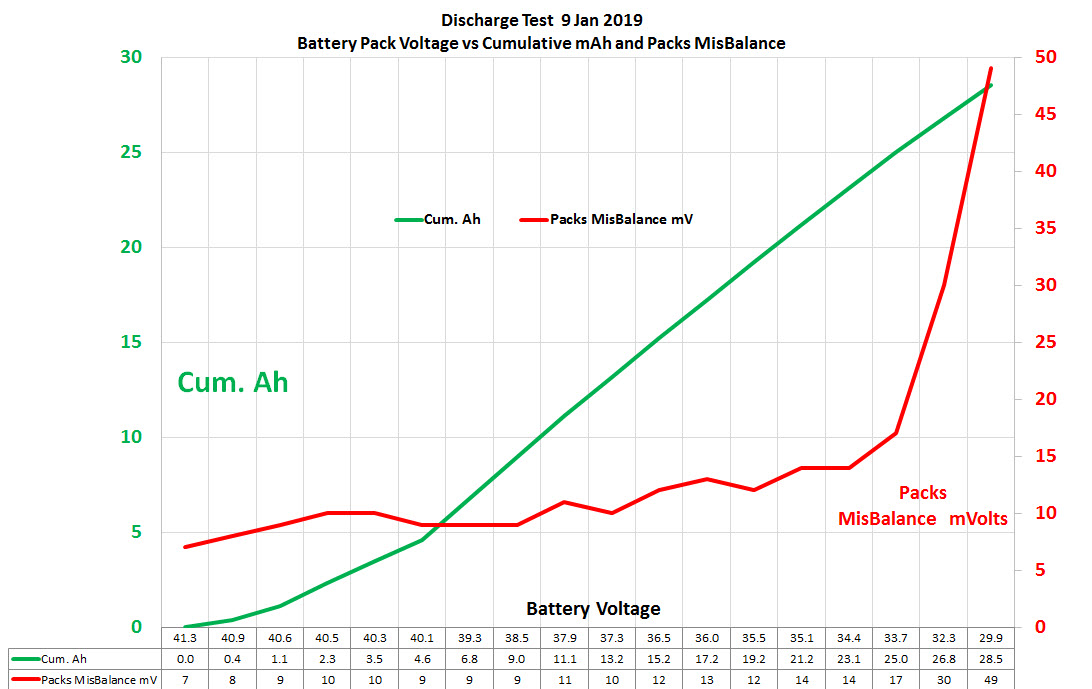
Discharge test completed on 9 Jan with headline results of:
• Battery Voltage at start of discharge test 41.5 V • Battery Voltage at end of discharge test 29.9V • Total discharge test time 420 minutes (7 hours) • Total discharge test Ah 28.5 • Total discharge test Wh 1,051 • Cell misbalance at start of discharge test 7 mV • Cell misbalance at end of discharge test 49 mV
Put discharge data into excel workbook for some graphs.
Initial impressions are that these Samsung 21700 50Es are very good cells.
Next is to do some real-life range testing!
16 Likes
Certainly shows why the default low V soft shutdown voltage on vesc tool is 34V for 10s What voltages are you planning on setting your soft and total shutdown???
Battery and vesc wiring all complete - powered up board and Dual FSESC6 unit with no magic smoke so all good.
Flipsky Dual FSESC6 connected to VESC tool 0.95 with no issues (units came with FW 3.40 pre-installed)
Ran motor detection OK and set-up normal master/slave canbus settings (with unit can-bus switch set to off for set-up)
FSESC6 settings as below
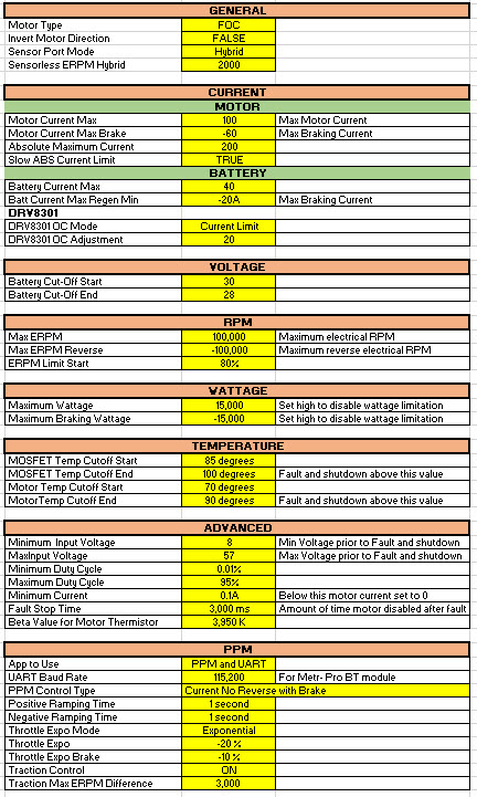
with throttle curve like this
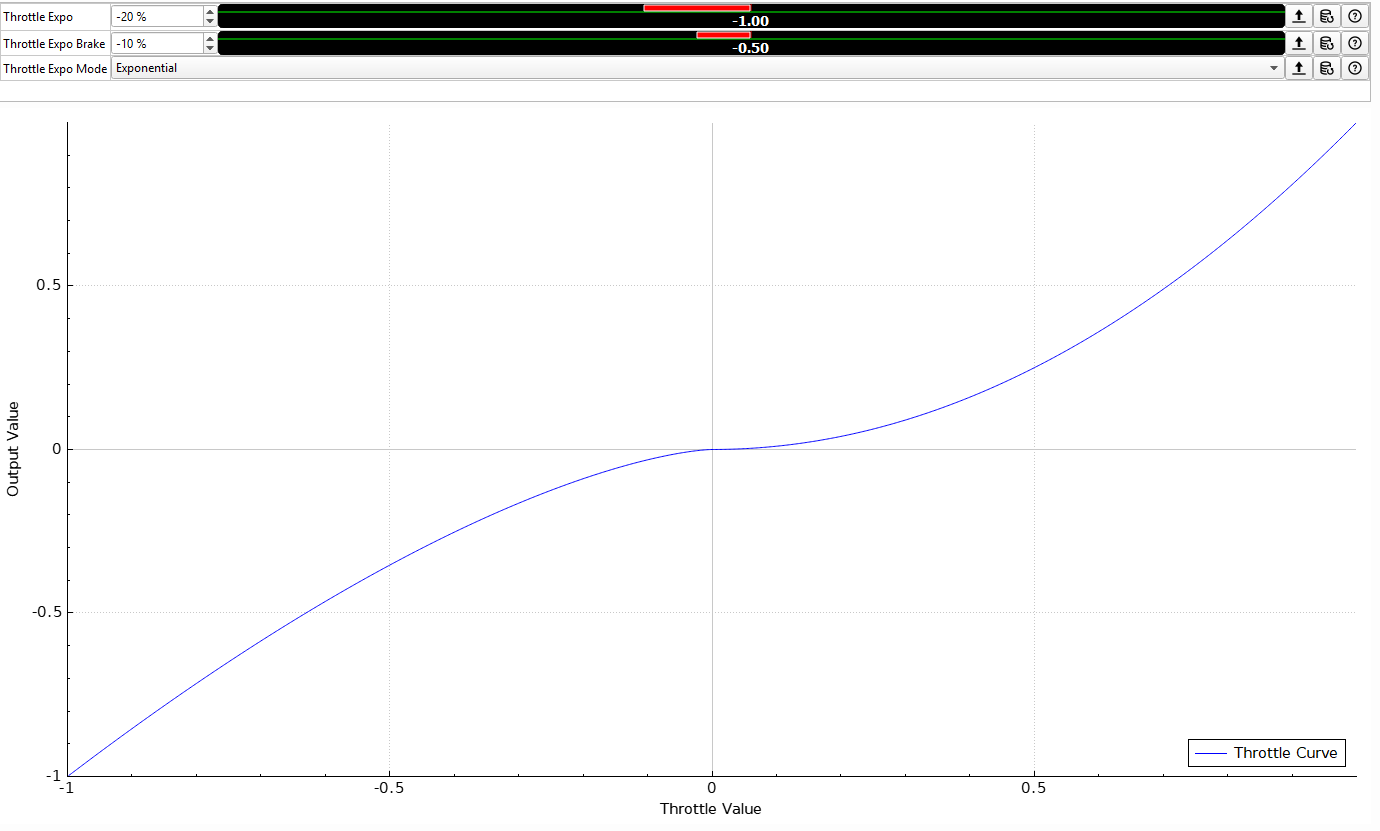
with first test ride up and down local street
Still a bit to tidy up inside board for auxiliary stuff such as headlights , brake light etc but for now it is ridable with range test ride planned next weekend.
8 Likes
How did you make that fancy excel with all the settings?
its called a keyboard!
lol, surely there is a way to automate the process as it saves as xml?
Its quite nice to have though, like a setup sheet for motor racing. Maybe add bushing and truck angles.
yeah - you can save config motor and app settings as xml file from vesc tool
No I mean like automatically convert the raw xml into a pretty excel that is easy to read/print. With some sort of copy and paste into a premade format. Im no excel pro though. Sorry to clog up your thread with stuff about excel. 
Woot - Board is ready to Roll!!!
2 Likes
Yes ! Make photos and videos ![]()
![]()
@lrdesigns, what is probably trying to tell you SkaterBoy58 , it’s maybe that he tap it itself C/P info from the xml vesc file to make a pretty tabler …?..
Good ride ![]()
Basic schematic diagram of board electrics - happy to answers any queries
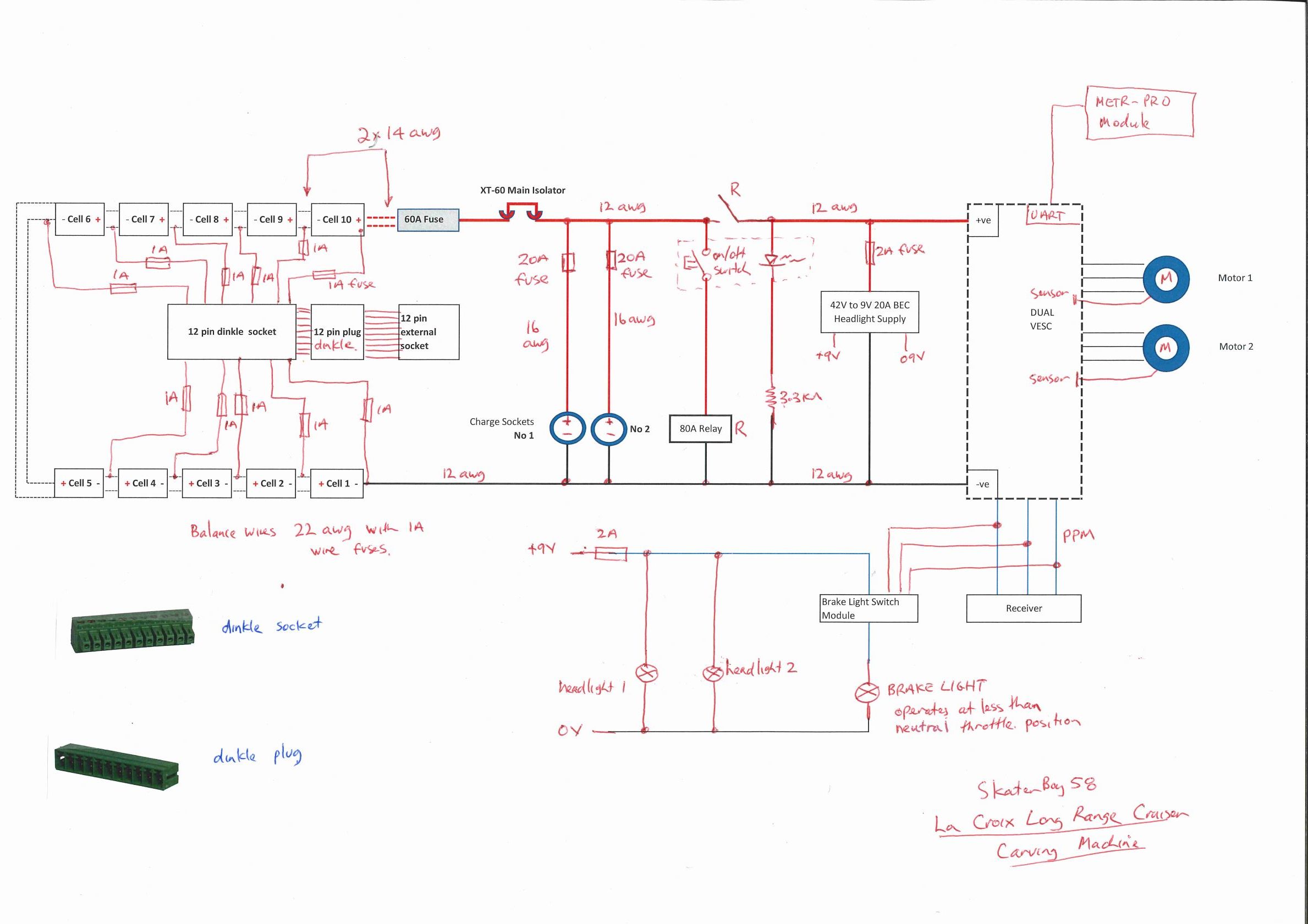
5 Likes
Very interesting to see a different approach to charging/power switch. Do you use two charging sockets to do very fast charge? You have a charger that can max that out and what current ends up going into each cell at max charge rate?