Right, now I see the resistor. So it’s a two-step process, first the bullet and then the loop key, right ?
first the XT60, then the bullet.
Love the idea bro, I plan on building something very similar. I have a question though, in the place where you soldered the copper cable to connect the two sides of the xt90, could I solder in a fuse instead? Basically right now I have a large fuse online on my negative power cable before the VESC. It’s 50 amps and made for a car stereo. It’s just so massive and annoyingly in the way. But if I was to put a nice small fuse, like one used on vedders anti spark board, 40 amp 50v I think. Would that work, or am I missing something in the way power travels?
@Rasmukri - that should work! The main concern i would have is resistance and heat.
I’ll see if i can grab one of the fuses i have and see how it might fit on the back of the XT90. Neat idea.
As always - having a spare to swap (anti-spark or not) is good peace of mind.
I’m not sure what you are proposing will work. a fuse and an anti spark resistor both serve different purposes.
I think you would have to put the fuse inline further down not in parallel with the resistor.
I cant see why it would be a problem. I mean its just closing the circuit, so instead of closing the circuit with a solid wire why not close the circuit with a fuse? Seems like putting it farther down the line would be no different. Power goes the easiest way possible and that will be through the fuse not the resistor, (after it has completed its job). I mean I’m no Engineer but I’ve been working on car and home wiring for quite some time. Resistors yes they always give me a bit of research before i do anything but i see no logical reason why a fused link would in any way not work. Think about it regardless of where the fuse is on the circuit the Same amount of amps will be passing through it.
by putting a fuse in parallel with the resistor you are changing the circuit. the fuse would still be the path of least resistance so in an over current situation it would probably still blow. but the amount of current required to blow it would change, and once its blown it would not break the circuit like a fuse is supposed to, because the resistor still completes the circuit. the most likely following sonario would be that the resistor would get really hot and also blow.
[quote=“rasmukri, post:26, topic:204”] I mean I’m no Engineer [/quote] True.
No, no, Nope no.
Hey LG - are you sure?
the way the anti-spark works it is only connected at that first few mm of plugging it in… afterwards it’s out of the way and not connected - right? or is it contacting and would then become the path (and quickly blow too)?
I’m no engineer…
if you are using an XT90-S that is the case. but not for the ones in the image above where the resistor is in parallel.
I apologise if that’s what you meant originally, I was looking at the pictures directly above with the resistor in parallel.
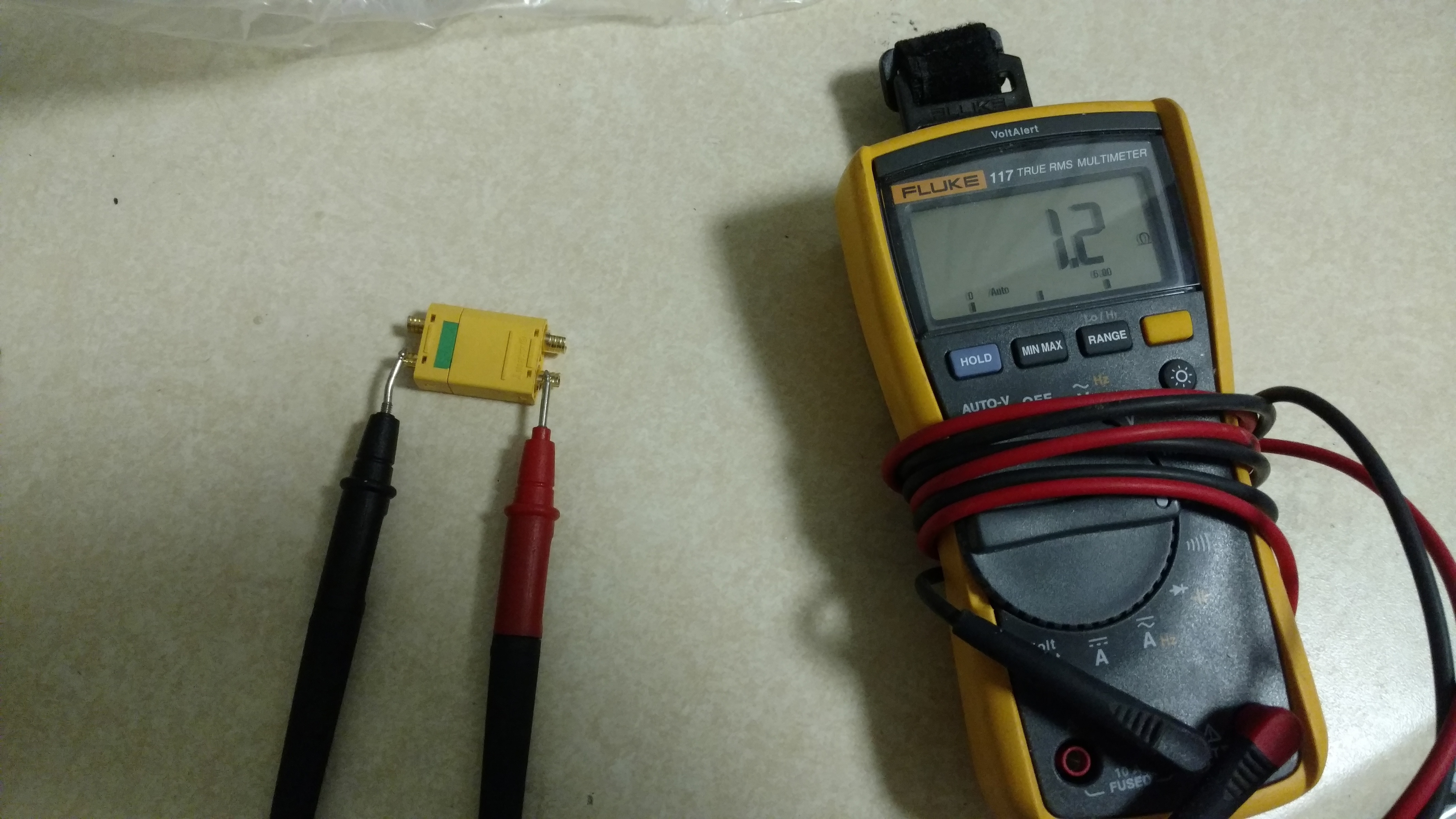
So I just got my xt90 in the mail today. I did a resistance test and it is 6.7 at partial insertion and 1.2 (for my voltmeter .65 is a direct contact between the two leads). So this means the resistor is not in use once the connection is full. Meaning if I put my fuse on there it should work no problem.


3 Likes
Yes that should work. clearly we were both talking about different things.
1 Like
Ok, I’ve left this way too long, but, after testing my initial loop key (with the 680 ohm resistor), I was still getting spark when connecting the bullet connectors, unless I waited long enough for the VESC capacitors to charge up (think 6-10 seconds, counting in my head every time!).
So I modified it and replaced it with a 47 ohm resistor. This way, as soon as I plug the XT60 in, the VESC lights up, then I can close the bullet connectors. PLUS, there’s no spark anywhere! I’m running 9S1P if that helps anyone.
2 Likes
I really liked your design so I went the same way, @sl33py! 
Here’s my take on it:

Broken off the protruding crescent moon bits and the inner plastic ridges.
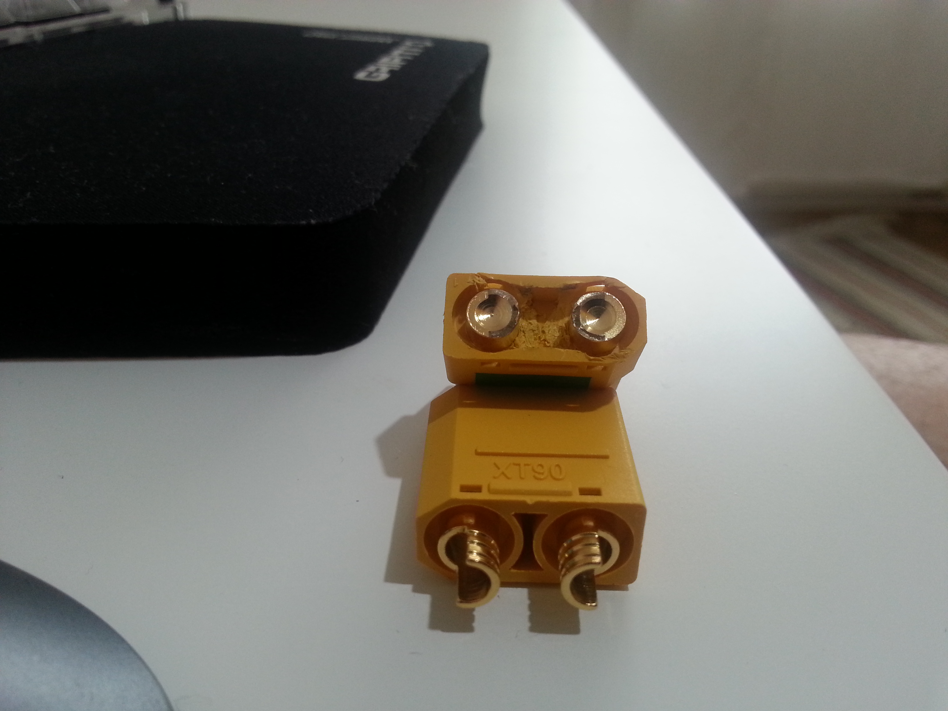
Soldered a bridge between the connectors like @sl33py did. I did it with two 2mm bullet connectors.

Pulled a bit of paracord underneath.


Shaved off about 2mm off of top of the cup and squeezed it into the connector with the paracord sticking through the opening.

Cut off a bit of leather off a belt…
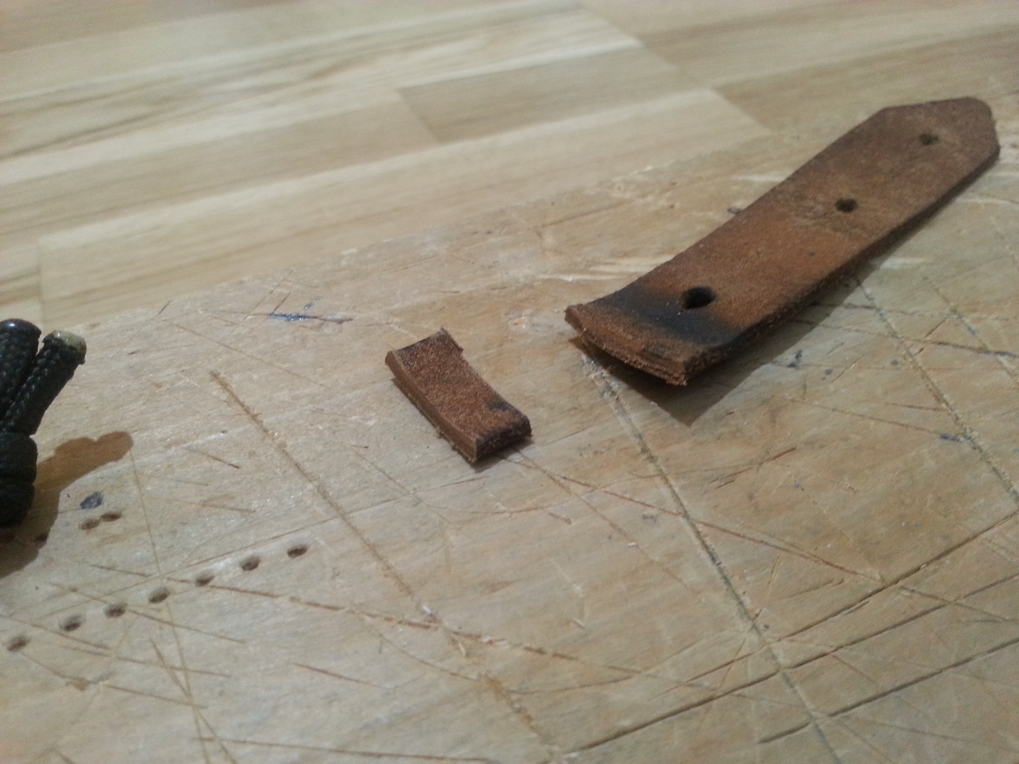
…shaped it into a tiny bone-shaped piece…

…and squeezed it between the paracord strands and into the opening of the connector cap.

Voila!
10 Likes
I have been doing mine this way for awhile, just never thought to post it.
I use a piece of 10g solid copper wire, bend the ends to fit tight in the XT90-S poles and then fill with solder. Then I cut the hald circles from the cap, super glue it in place and fill with hot glue. After its cooled some, just a little tacky, I push it in and then smooth the edges. It looks like this.

After that I print the XT90-S Fob cover, insert a paracord loop, melt the edges of the paracord together, fill the fob with hot glue and then insert the loop key. Let it cool and your good to go…ease to insert, easy to remote, the Fob protects the loop key.

Edit: link to Fob files
9 Likes

This is how I’m doing mine (the red Silicon wire is just to pull it out easily, the contact is actually made with copper wire inside)
6 Likes
How does this solder joint look on my loop key? First time soldering in a long time. Also - can I just wrap a piece of Paracord around that for a pull tab or not?


Bueller… Bueller
1 Like
Looks good, maybe more solder next time but no biggie. Yes you can use some paracord but I recommend shrink-wrapping it first.
1 Like
Thanks! So I assume I should almost fill the whole semi circle with solder? I did forget to tin them which probably didn’t help.
What you have is fine but you can just add more next time. Im not sure if you can fill the whole semi circle but just try and add a little more.
1 Like