Hello I’m about to start programming a double vesc setup.
How should I go about doing it??
Program one vesc and make it master then just connect canbus and make other vesc slave and that it, or do I have to program to slave vesc aswell?
Hello I’m about to start programming a double vesc setup.
How should I go about doing it??
Program one vesc and make it master then just connect canbus and make other vesc slave and that it, or do I have to program to slave vesc aswell?
Setup each VESC independently and then enable the can-bus
great thanks,
Im having another problem, sometimes my transmitter doesn’t connect when I programming the Vesc. Well it connects to the receiver as the red light comes on, its just doesn’t process the signal through the vesc. Sometimes it works after I replug it a few times, then I can see my signal on the pulsewidth.
Anyone know what the problem could be why its so inconsistent???
What kind of receiver are you using?
This one, im based in the uk. Standard 2.4ghz. So weird, sometimes the signal works and other times it doesn’t come on Pulsewidth bar.
Might be a low battery in the remote. Does it always work when you have the remote right next to the receiver?
i’ve been advised to skip the CAN and just split your bluetooth receiver so each vesc acts as a primary, as opposed to a primary+slave via the CAN.
in a primary+slave configuration, if the primary vesc goes out, your slave will stop working as well.
you’re building redundancy if you split your bluetooth controller into primary+primary.
so…take the 3 pin servo coming off your bluetooth receiver, split it into two 3 pin servo cables, then each of those get connected into each vesc.
just make sure the 5v wire is CUT for one of the two servo cable going into one of the vesc. otherwise you’ll be sending 10v to your bluetooth receiver, which is probably a bad thing.
i learned this from @psychotiller, btw.
Oh very interesting, but i do not have a Bluetooth receiver but im guessing it doesn’t matter itll probably still work with my reciever.
So the can the canbus be a bad thing or are people having problems with it, or is it just a measure incase your primary vesc fucks up and stops the slave from working as well.
what? isn’t this the bluetooth receiver for your remote?

not sure if canbus is inherently bad. nor do i know if people are having problems with it.
like i said, just splitting the connection gives you more redundancy.
Have had lots of trouble with can bus. I think the root cause was dry solder connections inside the R-specs. I’ll be splitting the connection next time. The redundancy it gives you is worth it alone. http://www.electric-skateboard.builders/t/need-help-dead-vescx-and-3-dead-vesc/18666
Honestly mate it could be im still new to this community. How do i make the servo split?
Which wire from the second vesc shall i cut so my reciever isnt getting too many volts?
That is not how that works. The VESCs are connected in parallel - you can not make 10V out of two 5V lines this way.
It’s still necessary to cut one of the wires. Connecting the two 5v rails in parallel will end up killing one. The reason is that you can have small variations in the output of the regulator, and if one is higher than the other then you’re sinking power into it which will burn it eventually.
@moe_lester That’s a 2.4ghz receiver not Bluetooth
Not necessarily
I had to reconnect them to make it work properly.
It’s got nothing to do with jitters or anything like that. You’re just stressing it. As I said eventually it will fail. Google connecting two 5v rails in parallel. There are plenty of explanations as to why doing this is bad practice
As you can see in the thread: it only started working once I reconnected them.
Also there is quite some contrary information out there with people saying one or the other. In the end I have not encountered a single case where NOT removing the voltage line had a negative effect. https://www.rcgroups.com/forums/showpost.php?s=e83ddd9f7650bc51c141657d79e53a11&p=14651248&postcount=11
I’m talking about electrical engineering here. Not RC forums. It’s not a good practice. They teach you that in school.
"In general, a power supply isn’t expected to operate in a redundant mode (i.e. with outputs tied together).
In industry parlance, this function is called OR-ing (not O-ring). If a power supply is designed with OR-ing in mind, there will be several additions to the circuitry:
Some means of isolation (diodes or MOSFETs) Some means of maintaining regulation at absolute zero load (anti-rollback) Some means of load balancing (forced or droop) These factors allow you to connect identical voltage rails together to provide load current beyond what a single supply can do, and allow for the rail to stay up (if the load can be delivered by N-1 units) if a single unit goes down. It also gives you some measure of protection if you accidentally connect a higher voltage to a lower voltage."
I am not sure what you want me to say: It did not work without the connection - now it does. In my case I don’t care what good practice is - I just want it to work.
I read your thread and it is obvious you have a failing ESC since it jitters on a single drive setup and has nothing to do with the receiver wires. Some component in it is faulty. What I suspect is going on is that your 5v line is dropping, which is causing the signal line coming from the receiver to jitter. By connecting the second esc in parallel, that esc’s 5v rail power gets pegged to the other and is most likely why it works.
I would not give recommendations based on a faulty setup. Yours works as long as the second esc doesnt start to jitter and as is you are putting an extra load on it.
The reason you are not meant to connect two 5v rails in parallel is stated above. You can take that however you want.
you’re totally right, not sure why i was so hung up on bluetooth. yes, 2.4ghz remote receiver.
no worries, i should have given you a better explanation earlier.
parts needed:
TWO 3-pin servo wire, male to male
ONE splitter, 3-pin servo wire, 2 female to 1 male - something like this

so, the MALE end of the splitter goes into your remote receiver, for me it’s channel 2 (yours may be different, test it out):

then the two servo wires are connected to the female ends of your splitter.
then each of the servo wires gets connected to your vesc.
watch torqueboards’ instructions on how:


here’s the part where you cut the 5v wire. but let me just explain why again.
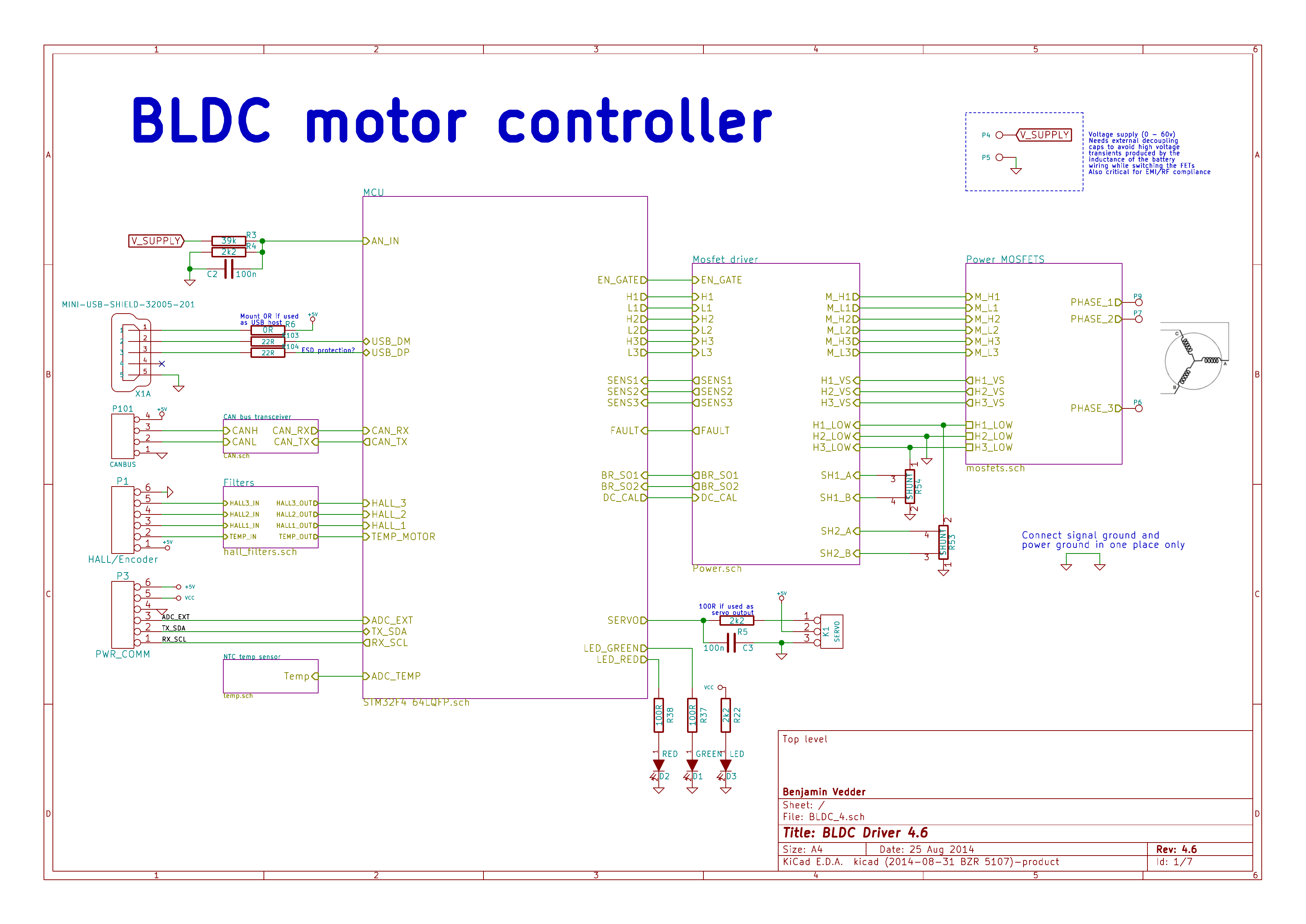
if you look at the vesc schematic, the servo connection outputs 5 volts through the center pin.
your remote receiver requires 5 volts to operate.
since we’re connecting two vescs, middle wire will now carry 10 volts to the remote receiver.
that’s why we cut one of the 5v line.
put together it looks like this, RED is the 5v line.

