potting alone will not help, I think. the heat needs to go somewhere. (in our case) to my understanding not all windings get the same temperature. (hotspots??) correct me if I´m wrong. so potting would distribute the heat better but as its an enclosed system the heat will stay inside the motor. so next step is to get out the heat
1 Like
I would speculate that the reason why hub motor runs hotter, is that it can’t dissipate the heat. So if you’re running the same power to a identical mass and construction materials belt drive motor and hub motor, both should warm up the same rate, but I think because belt drive motors are usually in the airflow all around the can (lots of surface area) it dissipates the heat more efficiently and therefore runs cooler overall. Hub motors have the insulating polyurethane around the can, so it can’t as efficiently cool itself with airflow.
1 Like
I like this discussion a lot but there is a lot of misinformation circling around. I am not an expert on VESC or BLDC motors but in physics and maybe I can clear some of the fundamental misconceptions:
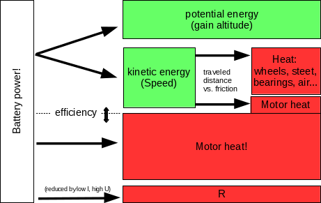
Of course people are right: hub motors are not cooled as efficiently inside the wheel. Even worse: there is rolling friction. Your board doesn’t roll forever because the kinetic energy is lost and heats your bearings, the road and your wheels. So the motor is right where you get most of the friction. But what most people completely mix up in this thread is the following
What actually heats the motor the motor in the first place?
Short answer: Losses! Not the Current, not the total Power.
The Power dissipating into heat is NOT the total power. Let’s consider a simple scenario for now: we accelerate, no rolling friction or air friction. Energy E is conserved, so E (P is the change of E over time), is split up into two main channels: kinetic energy K, and the loss L: E = K + L All the energy that actually contributes to accelerating you does NOT produce heat at this point. It will eventually since you don’t roll forever. But for now it does not. Only L. The efficiency is the portion of E that you can get into K instead of L. This is where @HTownBomber is wrong: a motor is not simply a resistor. The power consumed by the motor is P = U*I but that it not the power that dissipates into heat like in a resistor.
The statement that only P matters, not how you distribute your numbers in U and I, is wrong because the efficiency changes!
One part is electrical loss simply trough the electronics resistance R. The loss due to R is NOT the product of the total battery Voltage Ub, since only a portion of Ub drops over R: Ur. Only the rest of the power is USED by the motor. But the total battery current I passes through R: P = Ur * I = R * I²; This is the reason why we use high voltage transmission lines. You cannot avoid resistance altogether. So keep the voltage high and you increase the portion of Power that you can USE. But, as @Hummie pointed out, this does not apply to the motor windings: lowering KV reduces I but increases the resistance and the copper losses are the same. It does however apply to the rest of the electrical components and especially the ESC is more efficient at high voltage.
Apart from the electrical loss there are the typical BLDC motor characteristics. As I said: I am not an expert for BLDC motors but there are some rules of thumb that you can easily apply. The properties of a typical BLDC motor should look somewhat like this:
http://www.mellorelectrics.co.uk/BLDC-performance-graph.jpg
http://www.mellorelectrics.co.uk/BLDC-MOTOR-EN.html
N: RPM EFF: efficiency P: power I: current
This an idealized graph for ONE specific motor, and this is imporant: for one KV value (RPM/Voltage). One important fact that people should pay more attention to is that the maximum power is not where you find the maximum efficency!
To increase efficiency you should run your motor at a high RPM and low torque. This is why you should use a small motor pulley and a large wheel pulley in a timing belt setup. This can bring you to the left side of the graph, where the efficiency is high.
Also you can lower KV, which should more or less scale the x- and the y-axis. It will give you higher torque at lower current. Therefore you can keep the torque load further from the maximum that the motor can do. Reduce the speed, increase the maximum torque, then you can shift the maximum efficiency to lower RPM.
To estimate what “high RPM” means we can calculate some numbers: The largest gear reduction that you can usually get is around 12:36 . Let’s assume we want a maximum speed of 35 km/h (21.7 mph). At 83 mm wheels this means the motor will run at ~6630 RPM. The KV that you need for this at 12s is ~150 RPM/V (!!!). This way you can run your motor close to the maximum efficiency.
What makes hub motors become so hot? The lowest KV of a hub motor that I have seen so far is around 75 RPM/V, which leads us to a theoretical top speed of 52.7 km/h (32.8 mph)! So why do you not reach it? If you can’t get close to this RPM it means that your load is too high! You run at a regime at too high torque load, too high power (center of the graph), and low efficiency. Your motor will get hot because it wastes a too much of the precious power from your battery pack!
As you accelerate you climb up the blue curve (RPM) and the efficiency climbs up with it. Your motor has a comfort zone. But you can only get there if you don’t use all the torque, that it can offer. Here is a cheesy flowchart to illustrate my point graphically:
9 Likes
I like the graph you posted, helpful in understanding the characteristics of brushless motors, and the disadvantage hub motors have not being able to change the gear ratio. Makes sense to me, can’t just make a bigger hub motor, because the wheel circumference also increases.
@Mathias very good post thanks!
As mentioned above I’m working on part 2 of my article that is going to cover the stuff you mentioned, so thanks for contributing.
I’m also doing a chart that calculates some data based in input. Thinking about it I could use this sheet in order to plot a graph for various motors and extend it and include SPEED. This would then be the theoretical graph that we would have to verify.
BTW:while the graph in your post is absolutely correct, it is somewhat difficult to read and interpret! e.g. the unskilled eye could think that amps is the highest at high RPM while the contrary is true!
Yes, didn’t actually make it. The link is posted below the graph. I would also prefer @SimosMCmuffin 's post. It is less confusing. I was already thinking about making calculations like this on my own, or rather a simulation with proper parameters for an e-skateboard. Unfortunately I’m super busy writing a thesis at the moment. I shouldn’t actually be on this board right now… It’s just that e-skateboards seem 100 times more interesting at the moment:
that’s the universally agreed graph 
Not sure how many people really know what it means though, hahaha …
will try to draw the curves for specific boards or setups and showing speed in km/h as horizontal (x axis), then every eSkater can check at which exact point in power he is. This needs some assumptions of course.
Thanks guys for your constructive input!
@mathias, fully with you. At day time I should do some work, in the evenings I rather go for a ride on my eSk8 board than this discussion board and then there is family …
I’m planning on graduating this autumn and I plan to write the thesis about the ESC I designed and I should probably really start writing soon, but man. There really seems to suddenly be a lot of other interesting things I’d rather do 
Also I’m designing the next iteration of the controller at the moment.

2 Likes
I like this description, very enlightening and makes you think about the basics that should be obvious. I am not sure about the equation or what the abbreviation Ke stands for?
One thing I just thought of though is if a Vesc controls Voltage output and current then the best place to start is by getting the Vesc that can take the highest voltage input and matching that with a battery that nearly reaches the maximum capacity of the Vesc so regardless of motor choice it can run a bit cooler when modulated to the highest voltage rather than the highest amperage. What do you think?
voltage gets converted to amps or something to that effect and you’ll get the same heat to torque output regardless of the voltage of the battery. motors run on amps. higher voltage will be easier on the battery and generally easier on the esc too
1 Like
Most important point is a balanced system.
Motor rating, Kv, battery voltage, gearing, desired speed /torque. Then apply the proper settings.
1 Like
I think this discussion has two facets:
- Physical Motor Design
- ESC Design
We know we are asking a lot of a fist sized motor. 30Nm and 60kmh are a lot to expect from a stator that shouldn’t be much more than 30mm or so long with a diameter of 55mm or less.
We also know, @devin, that there is some funky stuff happening with the VESC. In brief, he has tried to understand the discrepancy between expected motor output based on battery/motor output settings in the VESC by examining the power entering and exiting the systems. If the current draw and voltage entering the VESC from the battery is XXXwatts and that same power leaves (minus some thermal waste) goes into the motor, we should expect XXXwatts worth of performance. This is significant because the VESC calculates the rms voltage from the available/set current. If this voltage is not significant enough to generate a field, more amps come to compensate (HEAT!). If the amperage is low, then the system doesn’t seem to compensate satisfactorily. (If I missed something @devin, let me know).
Since there are a lot of VESCs in the wild now, can we try to understand the VESC settings better before we drop cash on motor building?
This is fantastic. It helps me a lot.
Hi all XXX! :)
A hub motor gets much hotter because the small motor is required to output high torque, because of this, the motor amps are higher. More current = more heat and the motor is also trapped inside a urethane casing which increases thermal insulation. Enertion uses a great cooling technique for the stator which transfers the heat directly to a heat-sink truck!
Hub motors will get much better soon 