Help: Bestech 6-10s BMS shorted and caught fire while soldering

Hi everyone,

My Bestech BMS seems to have shorted and caught fire while soldering.

In shock right now… The fire extinguisher failed (fell out of charge…). Had to use a damp rag to put out the fire. Quite the disaster. Burnt BMS. Possibly burnt battery pack… Hundreds of dollars of damage… But all else is well, thank God.

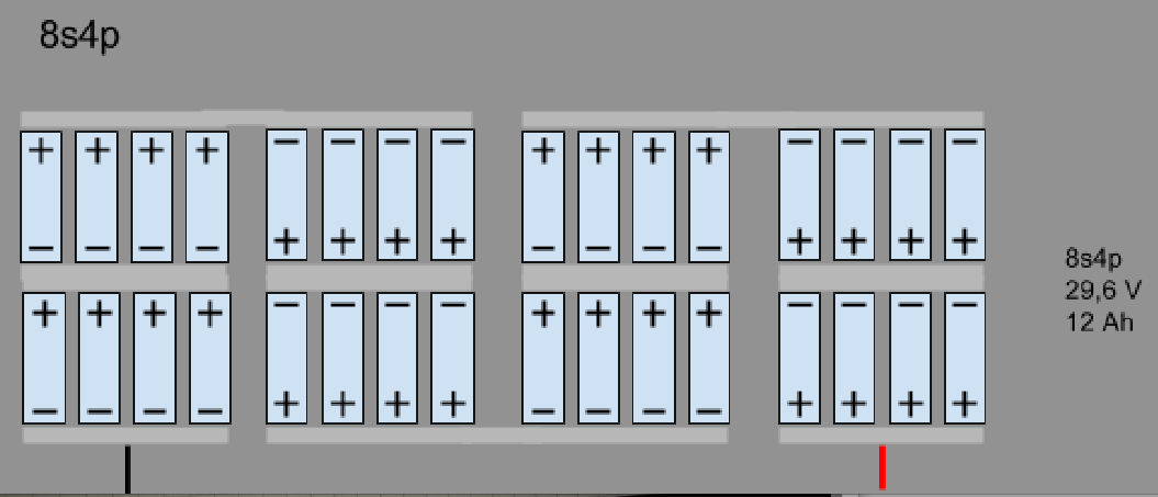
My 8s4p li-ion battery pack had been finished earlier, and I was on to soldering the very last wire to the BMS… A black negative lead (from the load / anti-spark switch / VESC) to the “P-”… Everything was connected except for P-. I’m really not sure how it all burst into flames?

The P- wasn’t even hooked up to anything, apart from an unplugged XT90! There was fire before I even connected the negative wire to the P-.

The last thing I vaguely recall doing was putting a droplet of flux onto the P- connection. I think so anyway, as I did that to prep the C- and B- the same way. It’s all hazy right now. Next thing I see is smoke and flames… Maybe the droplet was too big? Maybe it seeped through the PCB, connecting the C- (red positive lead) to the P- (black negative lead). – Looking at the underside of the PCB, these two connections are really close, like 1-2mm. So, maybe the flux seeped through?

It’s a sticky mess right now. Hot glue has melted everywhere. Even small melted solder puddles. A couple of nickel tabs came off the 1st series connection. Heatshrink has melted everywhere, both the original layer and the 2nd layer I added. But somehow the battery is still registering 25.7v (was ~26.2 earlier before the fire), so 3.21v per cell.

Is the battery ruined? What should I do? What went wrong? Should I try again and connect my 2nd BMS? I’m shocked and confused, uncertain how this happened. I thought I was doing everything right.

DSC03070|690x388

Uploading…

Details:

  • BMS Model: HCX-D223V1LI10S80A-06
  • Battery: 10s4p Li-ion, cardboard ring sealed, shrink wrapped each cell, soldered nickel strips
  • Load: NA. Nothing connected.

Please help if you can. Thank you.

1 Like

Ummmmm just for clarification. You didn’t happen to have the batteries plugged into the bms while soldering did you?

Hi ShutterShock,

Yes, battery was plugged into the BMS while soldering.

There was, however, no load connected. So the battery was not completing a circuit (not intentionally anyway). As per photos, an XT90 was just about to be connected. No connection to anti-spark switch / VESC.

Did I make a rookie mistake? I assumed that’s the only way, since BMS are often sold built into battery packs, and the wiring diagrams I trusted on ESK8 were the same.

E.g. @Namasaki’s

To illustrate what I was attempting before the fire: Burnt BMS vs New BMS with the wires I was originally trying to connect connected.

Perhaps someone with experience can confirm what went wrong? On closer inspection, I can only suspect the culprit may have been from excess flux seeping through the PCB and shorting the positive and negative terminals (C- and P-). :face_with_monocle:

The underside of the BMS PCB between the two terminals. It’s super close! Like 1-2mm close! You’d never notice on the topside.

Did you solder correctly the balance wires? Every bms units are “similar” but not the exact same. Some have 10 balance wires… some 11, some have charge and discharge in two ports…Some share the same port, some balance…Some do not. Did you get intructions with it? Some bms must be soldered in a very specific order. First -b then -c and -p and the last step solder and plug the balance. Just by looking at the pics I have no idea. It could be a faulty bms, incorrect wiring or incorrect order.

20180216_141203

That part worries me. The main negative looks too close to the positive and I see no insulation. Was it protected?

Thanks rojitor. No instructions I’m afraid. Vague directions on a datasheet, yes.

Yes, good point, I believe 8 balance wires were connected as per instructions from Bestech. Pre-purchase I clarified how to the balance wires worked: They confiemd that the BMS has “10 wires (B1-B10), but for 6s I only need 6 wires (B1-B6). Likewise, 8s would need 8 wires (B1-B8).”

Thus, for an 8s battery, I connected 8 balance wires (B1-B8).

Hopefully, they were connected correctly. I believe they were. I mimicked the position @Eboosted used in ‘Upgraing an Evolve GT Battery’:

I thought the positions were odd at times, but I went with it:

Diagram as per Bestech’s BMS Datasheet: 44 AM

That part worries me. The main negative looks too close to the positive and I see no insulation. Was it protected?

Good eye. But, no short there, I don’t think so anyway… Not at that point specifically.

The main neg lead (and leads and balance wires) have ample hot glue insulation, and have 3 layers of nickel strip (stepping up to that lead). i.e. ebikeschool’s diagram:

However, now that you mention it, two nickel tabs had come off nearby, but on the far lefthand side, between B1 and B2. It’s obvious in pic1 and pic2 (see op) where they’re separated (amplified by me lifting the esk8 out onto my driveway).

ALSO at B1, the cell right beside the main neg lead slipped out of place (desoldered and shifted out of position). Very shifty… I assumed it came loose from heat (heat overall from the short - you know, hot batteries everywhere, glue melting everywhere, etc) but perhaps that main neg lead you’ve pointed out somehow contributed to this!? Because, while the 4p packs came apart, that cell is the only cell to have slipped out of place…?:confused:

Also, I’m not sure if this is important, but the balance wire at B1 is on the pos corresponding end of the cell that the main neg lead is attached? Is that the correct positioning? Does it have any affect, perhaps on current flow?

Some bms must be soldered in a very specific order. First -b then -c and -p and the last step solder and plug the balance.

Good point! But I did B-, C-, then P-? And it was the final P- that seemed to cause the fire??

But in terms of order, I now wonder if my balance leads are backwards. But, then, it’s wired as per the Bestech diagram… and Namasaki’s and others have done it that way. Wrong placement maybe, but surely not wrong order.

OK. After double checking Eboosted’s it seems that the main neg lead is a culprit. It seems to have supposed to go on the other end of the 4p pack… which makes sense, since the series connections are placed diagonally across the pack. What was I thinking… So thank you rojitor, it seems that’s absolutely an error.

Yep, definitely an error. @Delta_19 had his main neg lead at the corner. His configuration is different though, but the leads are essentially the same.

But in @oyta’s diagram with my same configuration, his leads are centred?

I’d be happy to try anything at this point, but will relocating the main neg lead fix things and prevent another short?

And, if location of wires on the 4p pack is critically important, then, would improperly placed balance wires cause a short?

Thanks again.

Post detailed pictures of your battery pack. The location of the wire isn’t super critical.

Dont do this. You would have not shorted anything if the battery was not plugged in. Not saying that it would not have happened as soon as you plugged it in but yeah. You would have only seen big spark and melted the connector but everything else would have been okay.

E: I’m reading through your posts slowly, trying to figure out what went wrong :slight_smile:


Error #2: Is the pack welded or soldered? Looking at your second picture, if it was welded then your welds were weak. No weld should have come undone. If they were solder joints, then your battery is toast and consider yourself lucky that it didn’t catch fire.

Thank you PXSS.

To confirm, my balance lead wiring is practically the exact same as @Funktapus.

Same:

  • BMS Model
  • Wiring

But different:

  • Neg lead location. Like everyone else, he’s on the outside edge of the 4p pack. I’m at the inside (wrongly I suppose).
  • Charge port wiring. He’s before XT90. Mine’s not hooked up yet. It will be after the XT90, spliced with the anti-spark switch.

[EDIT]

Problem identified: Ah ha! I think I’ve identified the root problem. Wrong charge port wiring! See pic 3 with one red wire. Although it’s not connected to a load on the XT90, it shouldn’t have been connected at all to the C-.

I hard wired the main pos lead to C-, without a switch (i.e. charger). :blush: So effectively, I was charging the BMS / battery with the battery, effectively flooding the C- port with far more than the 2amps typical of an average charger.

Meanwhile, Funktapus’ charge port wiring (with black AND red) separates the main pos lead at B-10 (equivalent to my B-8) from C-, a critical separation from shorting the BMS and battery pack.

54 AM

But it still doesn’t fully explain how this short happened, because:

  1. The e-switch was _disconnected_. – According to the Bestech Datasheet: “During charging and discharging, The Switch should be on(connected)”. Thus, a disconnected e-switch should have had prevented the short, if it worked.

  2. The BMS has an over charge detection voltage of “4.28V±0.025V” (4.255-4.305v). Thus, since my 8s4p pack was registering 26.2v earlier in the day, it would have sent ~3.275v (26.2/8=3.275) into the BMS / battery, which is much less than 4.255v. More precisely, 0.98v less.

Please read and reply to the edits I make to my post above.

By “plugged in” I meant it’s all hard wired in, all soldered together. Maybe I’m missing something. I don’t understand how a battery is connected to a BMS without soldering it.

E.g. If a 4mm banana plug is placed between the lead wires, the result would be the same, as you say.

My BMSs have always come with balance connectors. JST XH connectors. Did yours not come with them?

Toast = damaged, or damaged beyond repair?

Battery is soldered, not spot welded. But it still registers 25.7v on a voltmeter? That’s 3.21v per cell, which is OK, right?

Yes, they came together, and I had them plugged in while soldering. Is that an error?

yes, you are not meant to plug in the balance wires via the connector until the rest of the connections have been soldered onto the BMS.

1 Like

Thank you DavidBanner.

yes, you are not meant to plug in the balance wires via the connector until the rest of the connections have been soldered onto the BMS.

Oh dear. I didn’t get that instruction.

Never have power on electronics when soldering if you can avoid it.

Definitely damaged, maybe beyond repair. It’ll have to be an extensive repair to make it trustworthy but it can be done.

I would suggest get them pulled and re heatshrunk

Thank you PXSS. How can you be certain? Is there a way to measure your conclusion?

Don’t know how bestech bms’es are designed, but on a supower bms balance wires should never be connected before battery + and - are connected or bms will fry.

1 Like

It’s my full time job. I design and build batteries for military UAVs. I’ve shorted plenty of batteries both on purpose and by accident and have honestly never seen batteries get hot enough to damage heatshrink in the manner yours is damaged without catching fire. Its either, they shorted out for a few seconds and are okay or they shorted out and burned.

Yes, there is a way but it’s not cheap. You need an RC charger that can measure IR. I use an iCharger 4010 Duo but that is definitely overkill for what you need. You can measure IR, capacity and balance the pack with it. Then you can compare that data to the manufacturer specs and see if you’re within the limits.

There is a way to measure IR manually but you need a good multimeter. Again, I use a Fluke 87V but that is overkill for you.


E: All the heatshrink damage seems to be on the negative terminals. Not one cell from what i can see on those pictures is damaged on the positive end. Did you damage these before hand or cut the heatshrink for any specific reason? It almost looks deliberate, it’s a little confusing.

1 Like