I hate to post another ‘why do my VESCs not work’ post, but I was really just after some confirmation and maybe a clue as to wether or not they are toast or can be fixed. I’ve read posts extensively but can’t find anything to match.
Scenario:
I finally got my eMTB spinning yesterday (see post here) and couldn’t wait to take it for a ride today. In my haste I took it out pretty much just with the batteries and wires held down with tape and only intended to take it round the block but got carried away and hit a few speed bumps, pulled a few spins, etc! Anyways, on the way back I only had half power and when I got home I realised that only wheel was spinning. On inspection I noticed that one of the XT60 connectors into the FOCBOX had come out so without thinking I just plugged it back in. This created a small spark (more of a subtle pop) and then I realised that I hadn’t unplugged the loop key to make the connection. I tried the remote and had no power. Unplugged the loop key, plugged it back in but the FOCBOXes didn’t light up
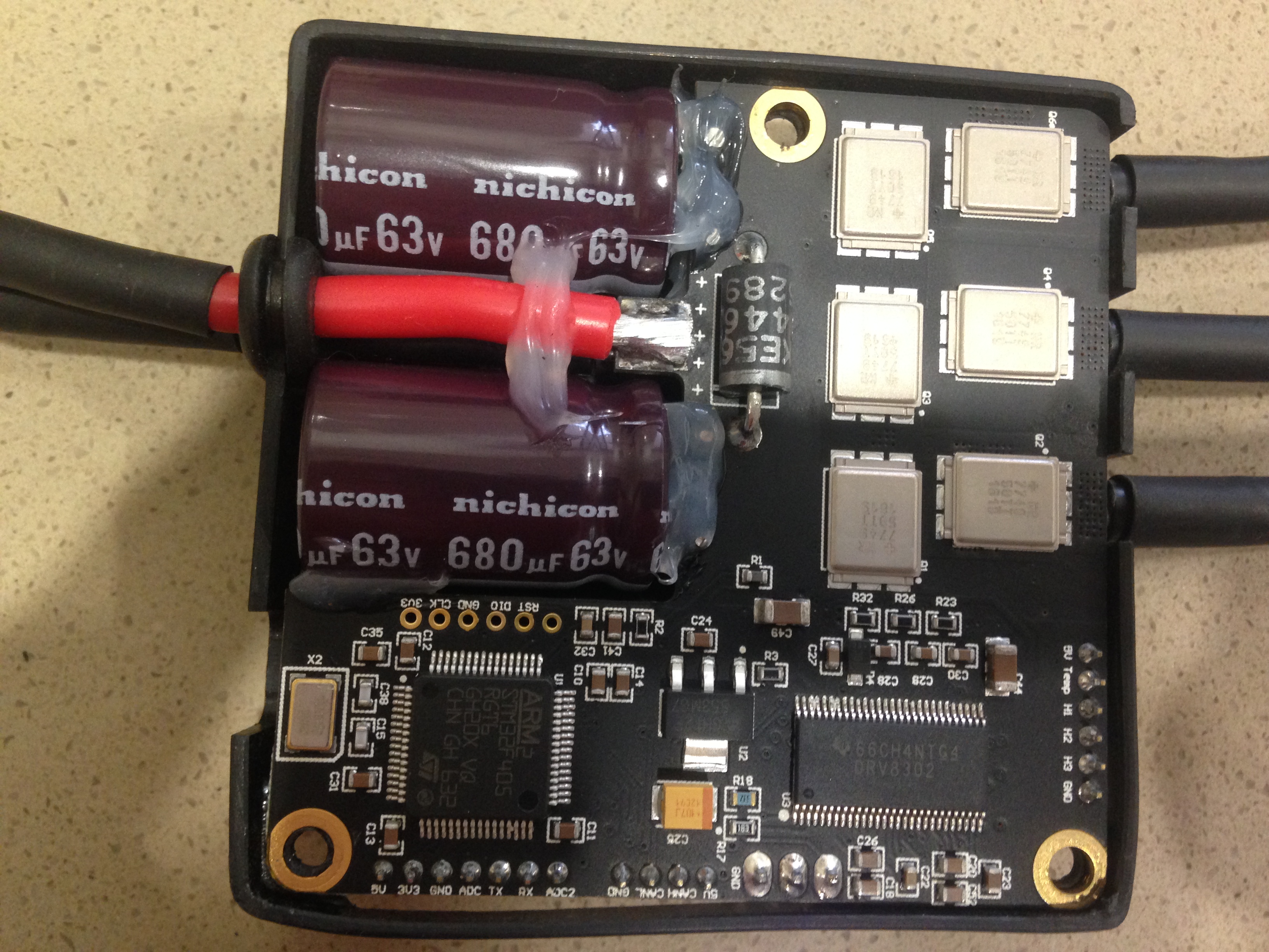
Since then I’ve tried all the tests I can think of; plugging one of the FBs into my esk8 setup, wiring up a smaller battery, plugging into BLDC with different power supplies (6s, 12s) and trying to detect. Both FBs seem to be completely dead. I’ve taken their clothes off and there is no obvious damage I can see:
Thanks for the info @Blasto - so would this prevent them from turning on at all? I’m currently getting nothing from them - no LEDs or anything and BLDC can’t detect them?
@L3chef any ideas who might be able to repair them? I’m in Oz but happy to post…
Yeah I reckon you’d be spot on there. I knew I shouldn’t be going out too with things not properly secured but I just couldn’t help myself!! And I was literally gonna go up the road and turn around but one thing led to another… Ha…now I’m paying the price!!
Lol, I’d love to say I’d give this a go but with my track record of things going bang I might leave this to a pro plus - I can hardly see half the chips on the board!
…out of morbid curiosity which chip is the U401? Scanned the boards but I’m guessing it’s not labelled as such?
Is the ground you are talking about one of the CAN wires or something else? I’m sorry for the stupid question, but this seems like something I could screw up. Thanks Blasto.
So I’m really toying with the idea of trying to unsolder/solder these chips myself. @JohnnyMeduse offers a fair price for repairing VESCs but the postage to the US and back is a killer so I want to at least explore the idea. After all - this is a DIY forum!
I’ve had a look for the chips and I can find stacks of VP232 (keyword searching: SN65HVD232DR) but the chips themselves all seem to have different numbers/characters on the chip. Can anyone tell me what the ‘62M’ AHEC on the chip refers to? Do I need to match this or just ensure the ‘M’ is within a similar range?
Thank you to all the guys who contributed on this thread - I’ve managed to remove the fried can bus chips and the FOCBOXs have sprung back to life!! Gonna use a split ppm cable now rather than can bus so I’ll be back on the road!! Still not sure if vescs are right for my build but I’ll secure them properly this time and do some proper testing.


 plus - I can hardly see half the chips on the board!