Haven’t been posting lately so here’s some pictures.

 Finally going to test the copper sleeves this Friday meanwhile I have this 12s pack (made with couple versions of holders, cuss I don’t want them to go to waste) all wired up. The final version is the ones with long nylon standoffs.
17 Likes
Dude. That looks great. The divide between the cutouts, channels the bms wires nicely.
4 Likes
Very neat build. No wire hell.
1 Like
Yeah I was pretty amazed too. Only temporary taped down tho idk how I should secure them semi permanently. Maybe I should super glue the wires together.
1 Like
Electrical silicone?
1 Like
Wonder if you could print holders as well that clip onto the wires running along the middle. Though tape is fastest and cheapest. Awesome work! They look better every update!
Cant wait till you can start producing these for others 
maybe use these with zip ties https://www.amazon.co.uk/Stonges-Adhesive-Cable-Mounts-Durable/dp/B01HR45KBA
Consider me camped out in front of your house in line waiting for one. I’ll be looking forward to whatever you use for an enclosure for your hummie deck as well.
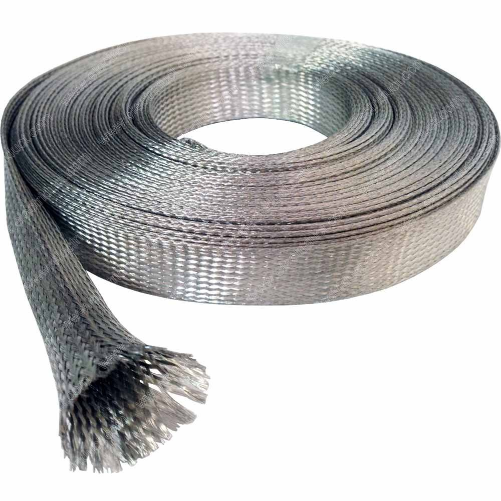
as promised I did a load test with those tinned braided copper. it works great. did 60A for a few minutes and only warmed up to 30-40C whereas the batteries went to 50C. found out there are different thickness of braid afterward but its getting to late to post everything so I’ll make an update tmr.
6 Likes
yay for updates! I suppose going for thicker braids would be generally safer?
As promise there’s the big update:
Didn’t know that there are different thickness of copper braid. I bought some 1.2mm and 0.3mm thick braid.
- 0.3mm - Seller list it as rated for 40A (right)
- 1.2mm - no rating available (left)

Since the thicker braid came first, I did measurement changes tailor to it so when the nylon standoff meets the cell holder on both sides it has a right amount of compression and not damage the 3d print.
you can kind of see the circular deformation at the top formed by the terminal buttons. This way there’s enough compression on the battery terminals without weakening the integrity of the cell
Testing with the thicker braid was pretty straight forward. This test is mainly for measuring the temperature of the copper braid during high continuous discharge to ensure it doesnt get too hot for PETG (80C glass temperature). The test was conducted on a 4p Samsung 30Q pack with thick copper braid (fully charged to 4.2V) with 10 gauge wire soldered to the ends of the braid. Using a 240W DC load, I drew constant current 20A, 40A, 60A (maximum of the DC load) for a few minutes while monitoring the temperature of the braid, closest to the opening of the cell holder and the batteries, with a IR thermometer gun.
The result is very optimistic. At the end of 60A constant current draw, Battery temperature was at 50C, while the braid only reached about ~40C. I also did a good old touch test to confirm that the braid was colder than the batteries. This video didnt capture everything but you will get the gist of it

Since the measurements are tailor to the thicker braid and it pass the test by very large margin. I will keep the current version and test the thinner braid later when I have time.
11 Likes
Nice test. nice clean fingernails
You think repeatedly getting the prints to an increased temp but still below the glass tradition temp could warp the print and relieve the compression? Be cool to see a repeated test and somehow gauge the compression after. Maybe just ride it and see if the resistance is increasing beyond what the little amount the cells would increase
1 Like
Damn that’s some nice gear! So jelly.
My 2 cents. I think electrically everything is up to and beyond specs. The unknowns are the mechanical properties, especially under tension, heat and vibration, over time.
The test is awesome though!
EDIT for grounding braid wire, I find mcmaster has a nice list with specs, and decent prices.
Scroll down to “Grounding Braid”
Whoops I typed this out but never hit reply.
I was doing the test at a electronics lab on college campus. I wish I have all that stuff. I want to test mechanical properties as well. If you guys knows how I can test that I’ll do it. I love McMaster but they don’t have the right 3/8" ~10mm and a good thickness available. Their price aren’t always the best for uncommon items and they use the fastest shipping and then slap you with the shipping cost after.
@Hummie I should dig deeper for PETG spec. I choose petg bc it has higher glass temperature that PLA and more flexible than ABS, which help with compression. Im not entire sure about repeated heat under glass temp damages the integrity of the shape. Not to mention that I did the test at 60A and I believe a normal load on battery is about 15-30a continuous on a dual setup and peaks to whatever your max Batt Amp is when you acelerate.
I can put together a pack with already dead cells and do a few heat cycles in a toaster oven.
6 Likes
I’m literally waiting on this to start a build.
2 Likes
Gonna make an update later. Stay tuned. Here’s some pictures from beta tester chat.


19 Likes
What chat is this?
4 Likes
Privalaged chat 
5 Likes
Update 11/21/18:
- Real life testing
-
I have been using the current design for the past few weeks in my 13s Hummie Build. Although I’m typically only ride on BaeSk8 group rides, our group ride can get quite intensed if you are at the front of the pack pushing 28mph uphill and doing 30+ on flats. and going up Twin peak at full throttle.
-
there are section with repeated cement gaps and rough street, also I rode on a already terrible road and there was hella small rocks(probably fell of some truck that day) to the group ride. So if your cell holders are properly padded they have no problem dealing with vibration.
-
[usable telemetry files] (if you wanna throw some metr module at me, you will get better telemetry)
-

-
Beta Testing
-
We have a few beta tester signed up for testing the current design with copper braid. as you read, these copper braid is way over spec our application and iti will stay this way. I am printing out single stack, 2s modules and stagger stack modules for these guys.
-
I’m confident in the compression and safety, but I know these will take a bit longer than NESE to assemble and would like to hear what they think about the process of putting them together. I’m trying to make these as noob friendly as possible so if you can follow instruction you an build a pack.
-
-
Since I already have all the dimension nailed down. it’s quite easy for me to populate all the configurations you will ever want.
-
single stack, aligned double stack, stagger stack
(upload://d1rXy39Y2YYBzN5F8t6Rup06oCP.jpeg)
- Aligned stack has additional standoff in the middle for more compression while stagger stack trim the height from 41mm to 39.5mm
-
keep it under 99Wh. multiple S modules. (single stack, double stack however you want)
- e.g. 2s4p 30Qs is 86.4Wh
-
-
Working on improving modularity
-
I’m looking to use ring connector in the next iterations to improve modularity. idea is to quickly connect/disconnect module by loosening the one end of the module and inserting ring connector crimped to the positive sided braid around the first terminal button of negative side of next module
- pic > words
-
NEW IDEA!!!
- Forgot to charge your short deck? Not enough range and want more fun?
- Introducing 1 piece small swappable packs at 10s2p 12s2p or similar sizes.
- Idea is to have Interlocking cell holders to form a small rigid pack. will be vulnerable to impact cus you will be carrying it around. so material and encasement will be explored. still in very early phase
- Forgot to charge your short deck? Not enough range and want more fun?
-
-
Gauging size of market interest and demand for scalability
-
I need to know how many people are interested in using these cell holders instead of NESE or spot welding services? A set of 12s4p (using 2s4p modules) took about 18 hrs to print at the moment and nowhere scalable with 3d printing. If there’s enough demand, I will make a silicone mold or even design something for injection molding for large quantities.
-
Pricing: i’m figuring out how much I should price these things and where they are placed in the battery market.
- here are some pros and cons I came up with. please open to discuss about the current state of design:
-


AFAIK spot welding service cost about $200ish in labor. with the advantages of taking off individual cells to replace them and modularity and compactness over NESE, these cell holders I hope to price them low if I can get produced in quantity.
How much would you pay for a full set of 10s4p modules? (USD)
- 40
- 50
- 60
- 70
- 80
0
voters
This is what you would expect to get for a 1s4p module + the braid ofc. with the current design and it will only get better.

How interested are you in getting some cell holder ?
- Take my money right now
- Interested and will order once it’s available
- Waiting for modularity improvement then I will order
- I don’t see this happening
0
voters
3 Likes
I’d say it is definitely worth 80usd if they are made from a silicon mold for a 12s6p setup. Because I ride 12s6p still.
2 Likes