Oops,
Old Math.
This is the updated document: https://drive.google.com/open?id=0B0zQsjKfE5R7dG9ldjhaSnBHSmc
Oops,
Old Math.
This is the updated document: https://drive.google.com/open?id=0B0zQsjKfE5R7dG9ldjhaSnBHSmc
the shared experiences on this forum show that you need around 10-20Wh per km on average. Please calculate how much current you’ll be drawing on average from this.
Your motor CAN do 60A - but you will rarely do that (or 50A for that matter). At speed the limiting factor is voltage - not current.
It is good practice to overspec the battery so that it can handle the abuse - but to manufacture cooling solutions on the assumption that you will ride at a constant 2000W is unnecessary.
Update 5:
Things are happening!
I’ve frozen design, and started production. Since my last post, some minor design changes occurred.
The most significant is probably the electronics move. In previous design iterations, the electronics were on bottom of the battery box. However, this pretty significantly reduced ground clearance, and left the VESCs vulnerable to impact. So, I moved them to the top of the board, and actually sank them into the deck a bit. They are also covered by a 3D printed enclosure, for safety.
This poses several problems, The primary being 3D printing the Top Shell. Since the 3D printer I’m using doesn’t have support structure, there’s a high probability that the shell will sag. So, I elected to add support Gussets, for construction.
Then, we will 3D print the shell upside down, and cut the gussets off with a razor later. Also notice the mounting shelves on the northern and southernmost faces. This is where i will glue magnets, resulting in a fastener free method of holding the shell to the board.The next design change is to the battery box.
The box now features removable doors, allowing access to the batteries for diagnostic and repair. Furthermore, it includes mounting points for the VESCs that will protrude through the top of the board. Other than that, It’s essentially the same.The other major change is to the wheel pods.
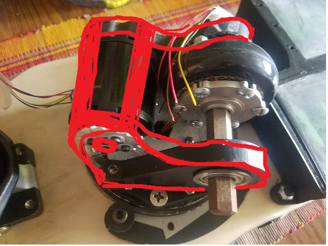
I moved away from hub mounted wheels to a more standard, chain drive. I have extensive experience using chain, and prefer it due to it’s lower space profile over that of belts.The axle will be 1/2" steel hex shaft, utilizing hex hubs to mount the motor and a 16t hex gear to drive the motor. The other gear will mount to the shell of the motor, and spin with the outrunner.
Now, Let’s move on to some physical developments!
First, I cut and validated the Lazy Susan Slip Ring. Everything worked surprisingly well!. There is some skipping between the phases, but i hope to remedy this with a diaphragm and polished race tracks.
Next, I cut the board!
I’m actually manufacturing two decks, one without inlay, and one with. The board without inlay is cut in it’s entirety, and the board with inlay still needs the purpleheart additions, and the holes cut. I used a ShopBot to fabricate, Essentially a CNC router. I started by setting zero, and cutting the top features. Then, flipping the board with the same zero, and cutting the bottom features.Cutting Decks has never been so easy!
I also started powder-coating parts. The black looks nice.
Up next are the battery packs. My pack will be a 6s5p pack comprising VTC5a 18650s supported by 3D printed runners.
I will be custom cutting bus bars out of 1/8" copper, and fastening it using silver-conductive epoxy.All in all, things are coming together!
Yours,
VillainousJ
So sick! How much ground clearance will you have under the motors? That seemed to be kind of an issue that @Nowind pointed out in his Leiftech abuse thread. Build looks great so far. 
Should have about 0.75" of ground clearance on the motors… I hadn’t heard about that abuse. Something to look into!
Probably the most informative and interesting thread on the interwebs about the Leiftech and it’s true performance and issues. Makes me want to find a cheap, broken one, just to upgrade it the way @nowind did.
Hello friends!
My deepest apologies for the delayed update. New semester started and i didn’t have much time to work on the board.
Anyway, let’s get down to brass tacks. As it stands, the board is about 90% complete.
Currently, both VESCs are powered and drive, but i’m having trouble getting them to run at the same time. I haven’t had the chance to get an oscilliscope on the CAN signal to determine the cause of the problem. However, the pods can be driven, and rotate as they were designed to! This bodes well for the end product.
On to the build updates.
I ran into several problems during fabrication. The first being with the batteries. I ended up building a VTC5a 6s5p pack capable of pushing 100 amps continuously. In order to carry this current, i custom cut bus bars out of 1/8th copper. However, due to the thickness of the copper, we were unable to spot weld effectively. So, we found an alternative: silver filled epoxy.

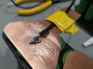
This same epoxy was used to mount the balance wires (seen above). After 10 discharge cycles, no issues have been seen thus far.
I also plasma cut the remainder of the pieces, drilled, tapped, and added other features. Furthermore, every piece was powedercoated, to provide electrical insulation, and for aesthetic appeal.


Wheels were mounted to hex collars using a lathe, and then placed on hex shafts along with corresponding sprockets.
Really the only thing that remains to be done is to cut the top cover of the deck, mount the foot holds, wire the hall effect sensors to the slip ring from above and below, and cut and mount the chain.
I hope to keep you updated, but likely won’t have time to work on it until Christmas break!
Best,
VillainousJ
Make sure you have the master vesc with “multiple esc over can” checked on the ppm page, and the slave needs “send status over can” checked on the app page
Master should have an ID of 0, slave an ID of 1 set on the app page next to the “send status over can” checkbox
Build looks amazing.
WOW now that we know silver epoxy sticks well beginners that don’t have a spot welder could use that to make there 18650 packs
I’m a bit sceptic if it will stand rough vibrations or even Jumps with the Board ?
It looks amazing !!
If you have Time, id have a few Questions.
Do you plan to “opensource” it or produce it ?
what Motordiameter are you using 50 or 63mm ?
It looks like there could be alot of Torque on the Motor-axle having the Sprocket on the unsupported end. I think it would be good to support the Motor Axle on both Ends, this might also be a good way to protect the Motor from possible Rock and cobblestone impacts. Possibly evene with some “fenders”
I have seen really bashed-up Leif-Board Motors, so that would be an amazing “tough-up-date”
Greets
Notger
Hello!
I have no plans to do any sort of production, as all the components cost me upward of $800, and the machining was on the order of 30-40 hours. The price point would be too expensive for people to buy, I think. I can take a crack at updating my CADs and posting them over the next couple months. They won’t reflect a bunch of little, on the fly changes i made however, so they won’t be anywhere close to “plug and play”.
As to your comment about the integrity of the motor mount, I ran the stress equations on the motor shaft and casing, it doesn’t look like there will be any problems. If anything, the teeth on the sprocket will shear.
The motors are 50mm 150kv 2200 watt motors from that one alien website (the actual name is escaping me at the moment). I agree! Fenders would be cool in later iterations. For now, I’m just trying to get the board moving.
I’ll keep you updated!
-VillainousJ
Yeah I’ve tried that.
For whatever reasons, the VESCs won’t hold the flash once I load them. So I can’t tell if the settings “stick”.
The alternative is just to build a Y cable from the receiver and just deal with any sync issues from there.
Thanks for your input!
-VillainousJ
I’m definitely interested in the CAD files, and i know what you mean, i made the same experiences (not beeing plug and play) with my CAD Projects.
Iwould be interested to see some photos of the Motor-Phase-Copper-tracks, → how did you design the contactor and the Tracks
greets
Notger
Notes on Silver Epoxy:
The spec sheet seems to indicate that it has very similar strength characteristics as normal epoxy. So, it should be able to hold up relatively well with a large enough contact patch. Considering it’s only holding thin copper bus bars, and the contact patch is the entirety of the 18650 ends, I don’t see any issues.
What about the specs on current flow? I meant like how much current can it safely carry before getting to hot and possibly melting
I haven’t been able to run the motors under load yet. However, having reviewed the spec sheet, it seems like it has a relatively low impedance. So it should run fairly cool. I think the trick is to have a thin layer over a large contact patch, to minimize resistance. I achieved this by laying down a bead and pressing the cells on one at a time. I’ll absolutely keep you posted!
I’ll do my best to get the cad files up sometime soon. As per your track question, I actually didn’t use brush style slip rings. Instead i cut tracks in 3 phases of aluminum and am running the current through aluminum ball bearings. Pics seen below. The real trick is to keep all three rings in contact at all times. To accomplish this, i used a compressible medium and a diaphragm, allowing the inner rings to “float” and maintain constant contact.
The inner slipring is simply to pass the Hall Effect sensor signals to the VESC. Most of the current passes through the lazy susan itself.