True the thing is a beauty, I will test when I get my Beta unit in a couple days and see if that mod can be done cleanly  Maybe we can sneak in a bit more clearance if needed.
1 Like
Please add the option to do so for a few extra dollars
Are screw in terminals for the power and phase leads possible?
Okay @Deodand then I guess that you just have two i_s_max limits, one till nominal Temp. is hit and another till T_max when the throttle hits really hard like on current vesc architecture.
Input voltage is irrelevant in max current/thermal testing. The voltage drop is close enough to be the same at 20 to 50V
1 Like
Out of curiosity: did you manage to squeeze all the tracks in a 4 layer design or you chose 6 layers instead?
1 Like
This is a 6 layer pcb, mostly for getting the power accross the pcb
3 Likes
6 layer 2oz. on all layers. lotsa copper
Previous design with 2 seperate xt60s was a 4 layer but when we switched to a single power input for simplicity we wanted to make sure we could move all those amps through the PCB.
2 Likes
You can inject current into the d-axis to counteract the magnetic fields of the permanent magnets… Currently all control is just focused on minimizing d-axis current and maximizing q-axis current for maximum efficiency. But you could probably squeeze out a bit more max speed by injecting d-axis current at the cost of efficiency. This is my understanding anyway but have only skimmed a few papers on the process so by no means an expert.
EDIT: to the curious just read the intro to this little document it gives a nice summary.
2 Likes
Hi @Blasto … that’s not our experience. Our testing shows this does matter. I understand it fluctuates outbound (and inbound) if V is related to your RPM. In our case, it’s not. Our system runs constant V.
So, for example, if you sustain V at say 48-52 (our system) and then run 30a inbound continuously (say 1440w) per motor, how long will it last?
Are you saying it can run 48v and 80a inbound ‘all day’, that’s nearly 4000w constant; more than we’ve seen testing anything else.
Maybe that’s the total of both, so similar to 2 x VESC 6 with heatsink at say 2000w constant each.
Thanks.
1 Like
We don’t have a good setup for loading the system with 4 kW output.
Yesterday I did a ride up a long hill and output total of 2 kW (~ 45-60 amps per motor at around 15-30 volts applied) for around a minute and a half and saw a temperature rise of about 15 Celsius. Video coming soon  . Mainly this was limited by the battery current limits and voltage sag of the 10s4p pack.
My guess is that your suggested use case 30 amps per motor at 48V could be sustained beyond 30 minutes and probably indefinitely if you give the motor driver an interface to sink heat into the air (mount it to a metal plate or something). You’re going to run into problems with the power input if you try to output 8 kW, probably would want to up wire gauge and change connector so you could take in 160 amps at 50V… ultimatley only testing can show whats possible in these kind of upper limit scenarios which are outside the range of anything an eskate would use.
3 Likes
Did some reading on MTPA control, just to make sure we aren’t losing efficiency because of wrong algorithm choice. My reading suggests that the motors we are using in Eskate are nonsalient, which is to say the inductance of the motor doesn’t change whether you are along the d or q axis of the motor. This is where I’m gleaning the information from, someone tell me if this seems incorrect. These are equations for MTPA:
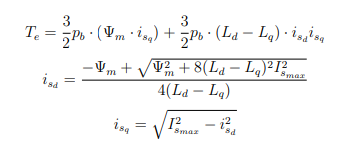
If our motors are nonsalient than Ld = Lq and simplifying the second equation for i_d yields 0. Setting i_d to 0 is what we are already doing… so problem that wasn’t a problem solved?
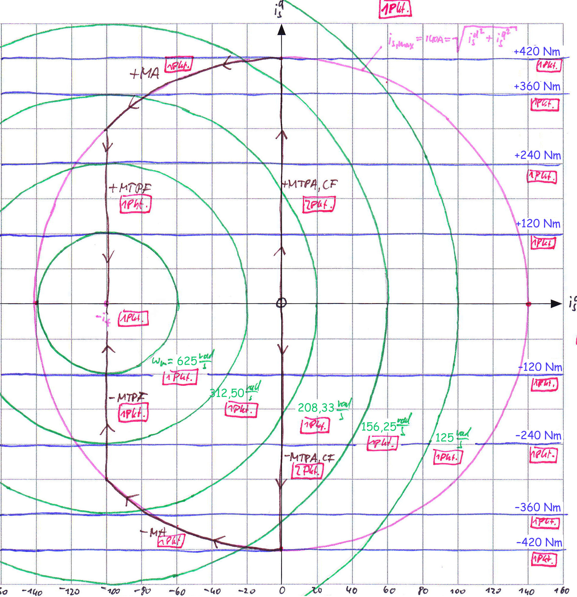
Setting isd=0 means that you operate at constant flux controll till you hit i_max. This method is more dynamic and is usually used in industrial aplications. In Electric mobility vehicles you would rather eliminate copper losses by sacrificing some responsiveness (moving i_sd is slow…). That’s why MTPA is used.
Regarding field weakening. The problem is that at higher speeds we would loose braking torque. On electric cars it is ok because of the mech. brakes, but on our application not…
MTPA was on Benjamin’s ToDo list. I guess it is way more complicated to code than it seems…
1 Like
Based on what I have read it seems that MTPA for the nonsalient motors we are using is equivalent to setting Isd=0, Can you point me towards something to read on the topic that would suggest otherwise? Thanks!
Here is another source where they use a nonsalient motor and set isd=0 for MTPA. See their description of region I (fig. 1) for MTPA where the condition is given as isd =0 for a nonsalient motor:

Sorry, I looked it up and you are right. If L_s_d = L_s_q the CF curve is exactly the same as the MTPA…
Sorry for messing up…
I guess that Benjamin was planing on further expanding the capablilities of the Vesctool SW for more exotic motors.
1 Like
Any eta on release like say in the next 3 weeks or so?
1 Like
It would seem foolish to release this in the next 3 weeks – that isn’t much reliability testing that could be done…
2 Likes
From what I heard from support, they’re not going to release until around september