you can get away with just using your battery as a power source when programing the vesc. maybe use the half to be safer.
an on/off switch has to be high power or will break quickly. I’d just use an xt90s plug and be done. maybe make an xt90s loop key.
@Hummie What do you mean it has to be high power, is there something in particular I should look for in a power switch? You said maybe to just use the XT90’s plug and be done but what do you mean by that, can you extrapolate a bit for me? Also what is a loop key? All the advice so far has been incredibly helpful!
it will spark and you can definitely just plug it in to start. I always jump when i do it…
A way to eliminate the spark is to use a loop key with a XT90 anti-spark. Instead of a switch w/ inrush control and complexity/cost (though nice).
A super old how-to i did almost 2 years ago now (damn time flies):
GL!
1 Like
switches seem to always break anyway.
I’d make sure your vescs are totally good and have all the parts and can do foc and a warranty too. I forget your plan but you could surely get away with one big motor and one vesc. or i see you already have them
How do you set up your battery enclosures so you can access it to plug it in and turn it on easily but also keep the water out of your compartment?
Also the XT90 anti-spark plugs I’m reading about, should I have them switch out the connections to those? Are you guys basically suggesting that to start the board each time I just plug in the XT90 connector to the vesc to turn it on with an anti-spark XT90 plug? From what I read on the loop keys it looks like its just a simple connection with a button on it. I am definitely not the most technically minded, do they make XT90 loop keys with those little buttons on them? The button seems much more convenient to hide than that big wire connection.
you could use silicone in a tube and coat things but I’ve never done it and don’t like riding in the rain. my stuffs still just held together under the board with duct tape still and using an xt90s and it’s ugly but performs. I have a bunch of extra tape all over the deck for the future. very ghetto but beats wasting time for me and I’ve yet to read of a switch or even a bms I’d want to use.
Okay watched some stuff and got a good idea of what a loop key connection looks like, my question now can I use a loop key anti-spark connection like that to power on the vesc to program it? I would assume yes but I feel kind of like a ditz here trying to figure this all out. If I set up a loop key connection like that all I have to do is plug in the little key and it will turn on? Does the connection on the looped part just send an on signal to the wires basically without having to have a physical power switch? How vital is it that I get the anti-spark stuff too? On my leiftech when I plug in the battery I plug in two xt60 connections to power on the PCB board, they don’t look like they have anti-spark on them and they make a sparking sound when you plug them in which I always just assumed was normal. Is that sparking sound bad for the VESC somehow and that’s why I want the anti-spark connectors instead?
the spark isn’t a big deal and will just mess up the connectors. the loop key just makes a complete circuit as if you’d plugged in your battery it just has the little loop making the circle complete. if the vesc gets connected to the battery it’s on. the bigger the voltage the bigger the spark. id just use an xt90s plug and be done. it sounds like you were doing the same anyway just without the antispark feature. supposedly not bad for the vesc. maybe a bit rough on the capacitors that lead to the vesc as they instantly take up the voltage and charge up but …that’s splitting hairs and caps last a very long time. some people chose not to use an antispark as then, when they don’t get a spark, they know the big capacitors aren’t working and that will ruin the vesc quickly.
The spark just depends on the voltage you’re running. Like @sl33py mentioned there is a large inrush of current that happens when the connection from the battery goes into the capacitors attached to the VESC, the caps can take in a lot of current really fast and if the voltage is high enough it will be able to jump across the air a tiny bit and just as the connectors come near contact there can be a big spark.
With regular XT-90s you’re fine with lower voltages but when I started messing with 12S and now using 10S it became necessary to have some sort of antispark otherwise I was burning up the contacts on the XT-90s with the sparks. Like others said here already though if it isn’t causing you problems a little spark won’t fry the VESC (even the big ones I was getting just fried the connectors).
Having a loop key (anti-spark plug with a loop) is still a nice thing to have though it’s a simple way to completely open the circuit if anything ever goes haywire and cuts the batteries from the rest of the electronics so the whole thing is basically guaranteed to shutdown (as soon as the caps drain, basically immediately).
I’m working on redesigning my battery pack right now I’m going to see if I can design a shell to wrap the 5S LiPo batteries that can be locked in tightly but easily be removed… with XT-90s on the hard shell surrounding the battery… basically like a network attached storage drive bay but for batteries. Currently the battery box I have just has 3 XT-90 female jacks sticking out of it for charging the two batteries and the third for the loop key but it’s a bit dangerous since if the loop key goes in the wrong jack it quickly becomes an expensive not very effective little bomb (redesign will take care of this issue too).
Okay so I have an anti-spark xt-90 plug coming in the mail now, my friend told me he would help me solder the loop key from it so that’s one check down, just gotta wait a week for the part. Waiting on the remote at the end of the week and then I should have roughly all my components together. The only thing I’m missing is my battery enclosure still which I’m still looking for a cheap solution, just haven’t found what I want at the local stores I’ve checked yet, gotta keep looking. Can I make some holes on my enclosure to make it easily accessible and run it without the loop key in the meantime? I might buy two of whatever I get for an enclosure and close it up more when I get the piece for the loop key if so, then I could be riding this weekend theoretically which I am very much YES to.
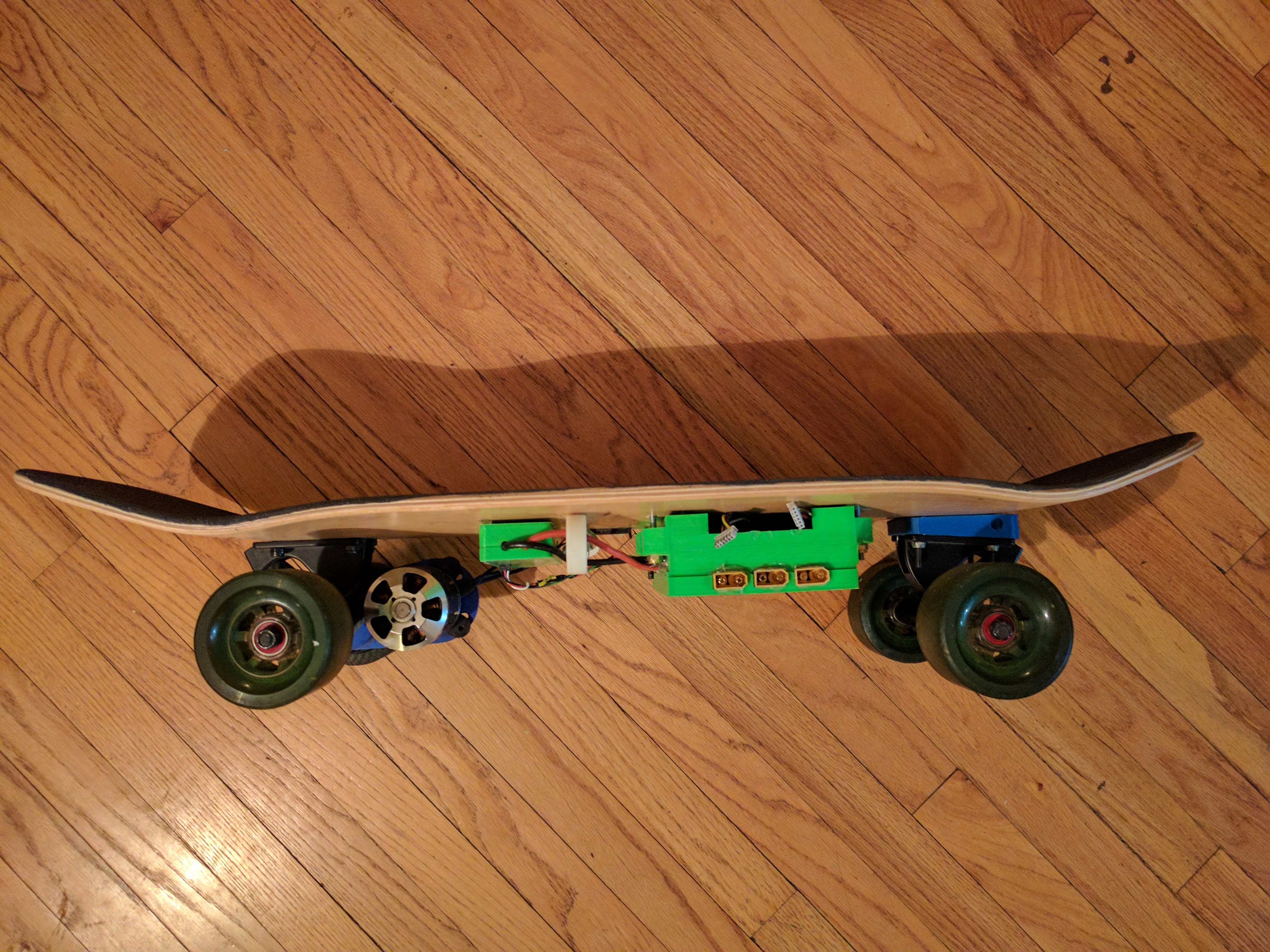
Secondly if you look at my photo I posted I had them rig up a xt60 connector piece where the battery can be plugged in from the outside with separate xt-60 connectors that go outwards for charging. My question is could I get a big battery compartment and theoretically put “two” of my 7s3p leif batteries in it using those connectors? I’d have to put on double risers but I would get a ton of extra power from it, and my leiftech is waiting on some parts currently so using the batteries in-between paychecks until I can afford a 12s4p is no big deal. Thoughts?
Edit Note: People have been asking about the Leif battery, turns out it’s 7S3P.
Yeah regarding the enclosure you can just put a hole in the side of it for running the two silicon cables from the battery(ies) to wherever you put the VESC (somewhere near the motor). When I was starting my first build I just used some XT-90 connectors to make a Y cable that would hook the batteries up in series like you can see below (I just ordered a handful of XT-90 male and female connectors at some point).
The male connector in the picture with the red and black goes to the VESC you could have this cable inside the box with your batteries and then just the cable that plugs into that red and black connection comes out of the enclosure and goes to the VESC. I just replaced one of the connectors on my battery with the anti-spark one so I’d just hook up the regular battery first then the anti-spark one second (you want to have the antispark one be the last thing you connect to complete the circuit it can’t just be in there).
Regarding skipping on the loop key and anti-spark plug, I’d say the no anti-spark is fine, the no loop key is also okay, but really good to have the loop key on there in some way you can grab it and pull it in case things go haywire at least you can cut off the power. So ya know, it’s all up to you really on what you do, personally started without a loop key too, but I find it to give me quite a bit of peace of mind that if the board goes crazy at least I can cut it off.
My board has three connectors sticking out like you’re describing and I cut the silicon wires that come off the batteries to give me leads that go to the VESC (regular leads go into the connectors for charging and stick out the side of my enclosure).
When I plug the loop key into the center connector that completes the circuit and for charging I just use the left and right connector separately. The danger here is if i accidentally plugged the loop key into one of the batteries I’m just shorting it out (again expensive crappy bomb). I’m reworking the 3D designs and prints right now on this so I can have trays that I can pop in and out just to make it easier to carry a couple extra batteries and swap on the go plus extra bit of safety if I can pull the batteries off the board quickly. In the redesign I’m going to have the shells around the individual 5S 5Ah batteries with the male XT-90 sticking out and will plug into the female port that will connect everything… basically what it is right now but flip the two outward facing ports inward and then I just slide the cells out to charge… it’s overcomplicated and extra paranoid, but I like it that way 
Additionally Since you’ve got 7S you’d probably want a parallel cable I imagine to just get more Ah out of the whole thing not more Voltage so you’d want to do a parallel style connector between the cables not the series one I linked above.
Other pics of my board here, not sure if they’ll help though since there’s some voodoo going on under the enclosure I didn’t really document here yet:
Ignore the white loop around the cables coming from the battery to the ESC but might help give you a better idea, I’ve actually got the guts all open right now so I’ll get some pictures of that too and put them on the github later.
@wafflejock So that’s awesome and probably close to what my zombie will look like, at least it will perform better! Not sure my friends can help tomorrow and I can’t bare my excitement to get this thing moving. I get the remote probably early afternoon and then I can set up the vesc finally. I’m sticking to bldc until I’m more experienced. Knowing what I know about the battery being 7s3p, 24v, 144wh are there any values ill need to plug into to bldc tool for those values? I have the 190kw motor but I can auto detect the motor settings in the program correct? I wanna make sure I don’t do anything too serious without having an idea what I’m setting up.
@Jinra @Hummie @sl33py @wafflejock @lowGuido
I’m trying to hook up my vesc and do a bench test, I hooked everything up like in the videos but when I power it on the vesc light stays flashing pink to blue instead of going solid blue, when I try to connect in BLDC tool it won’t connect there either. Can’t figure out what I’m doing wrong here, xD help please!
After plugging in the VESC and trying to hit connect give it a few seconds and hit connect again a few times, occasionally I have issues with the serial connection not being immediately available. Not sure about the constant flashing though haven’t seen that one.
Did some quick googling looks like it might be the DRV chip got blown somehow or was defective but if you can get a connection to the VESC in the BLDC-tool it should give an error code that would help to narrow it down.
Can’t get a connection, when I click connect it says “no firmware read response” and then says disconnected, but when I plug in the USB my computer recognizes something has been plugged in. Knew this was gonna be the pain in the butt part xD
Some clues here maybe http://www.electric-skateboard.builders/t/vesc-does-not-connect-or-stay-connected-on-ubuntu-or-windows/803/4 (maybe com port conflicts or something) and yeah the software is a mixed bag, can be a pain to get things to connect if they aren’t working 100% or just have weird config things different computer to computer so can always take some finagling to get it connected on the plus side once you get it working the software gives you a ton of info about what’s going on with your hardware (once you figure out how to understand it). Hopefully nothing major with the flashing LED issue.
Any luck yet? You may also want to try a different USB cable or port some cables and vescs have been finicky on me with regard to the cable too.
I’m out chilling with some friends at the moment but I’m gonna try putting fresh eyes and try Apple vs my PC with it in the morning, see if any better results.
Tried the apple computer today, same results. VESC continues to blink blue to pink, remote shows pairing, computer shows there is a USB device inserted but can’t connect it and can’t control it, it honestly is very much the same as in this video https://www.youtube.com/watch?v=2L82ARqBDAk waiting for Dexter to get back in today for some support with it.
Have you tried a different cable?