I will reuse some Longboard-stuff I allready own:
ABEC 11 Flywheel 90mm
Bear Polar 180mm trucks with spacer OR gullwing sidewinder
One of my decks
Ceramic bearings
I hope that sounds like a good setup?!
I am unsure about the capacity at the moment…
Do you have some further hints for me, which I have to take care?
I’d get a better motor mount. I don’t trust the universal fit style of mount. There are alot of people on here that make mounts. Hit them up and get a decent mount. You should think about a 10s4p to use with your vesc or upgrade to a focbox.
I wanna give that motor mount a try. Can change to some other or DIY later.
WHY shoukd I change to 10S? And why 4P instead of 3P?
Why would upgrade to focbox make a difference? Ok, they use diffrent FETs, but still very close layout to VESC 4.xx, right? So they also use 2 Shunts for current measure? VESC 6 uses 3 shunts.
Do they measure lowside or inline the phases?
More batts in parallel, less voltage sag. Go for 30Q instead of 25R.
10S4P with VESC and 190kV motor with 15/36 drive on Caliber II’s is a gold standard (proven setup) in esk8 atm.
VESC don’t handle 12s battery packs very well. Well they can but you got to be careful with your gearing and your settings or your blow it. Upgrading to focbox would be much safer, and a little more forgiving. Or go with a 10s4p.
25R have 20A each. 3P means 60A!
30Q just have 15A. That means only 45A @ 3P. Why do you prefere the 30Q then?
Change gearing later is not the issue.
I have those trucks mounted on my boards atm. So I want to try one of those.
But can handle Voltage: 8V to 60V (Up to 14S LiPo Voltage), right? So 12S shouldn’t be an issue.
WHY is focbox much safer and forgiving?
I prefere sealed and sensored motor. But since it has 170KV i really want to go for 12S.
@Luuke The cell ratings are often false. In this case the samsung 30q cells perform better than 25rs because they have a lower internal resistance, less voltage sag. When picking cells is it smart to look at discharge graphs found on google, there is a vape guy that does all the independent testing. You dont want to run electronics at their max, leave some slack. I would recommend running at 10s if you want lessen you chances of future issues. Focbox is an improvement over the 4.12 vesc, they solved some issues and made it more stable and powerful. It is still a Vesc which means it is not bulletproof.
Just installed my 90mm 83A Flywheels with fresh lubed Amphetamine Ceramics Gold bearings.
On long term I will try to use my 80mm DTC Concept wheels. I really like those wheels with great urethan component the aluminum core.
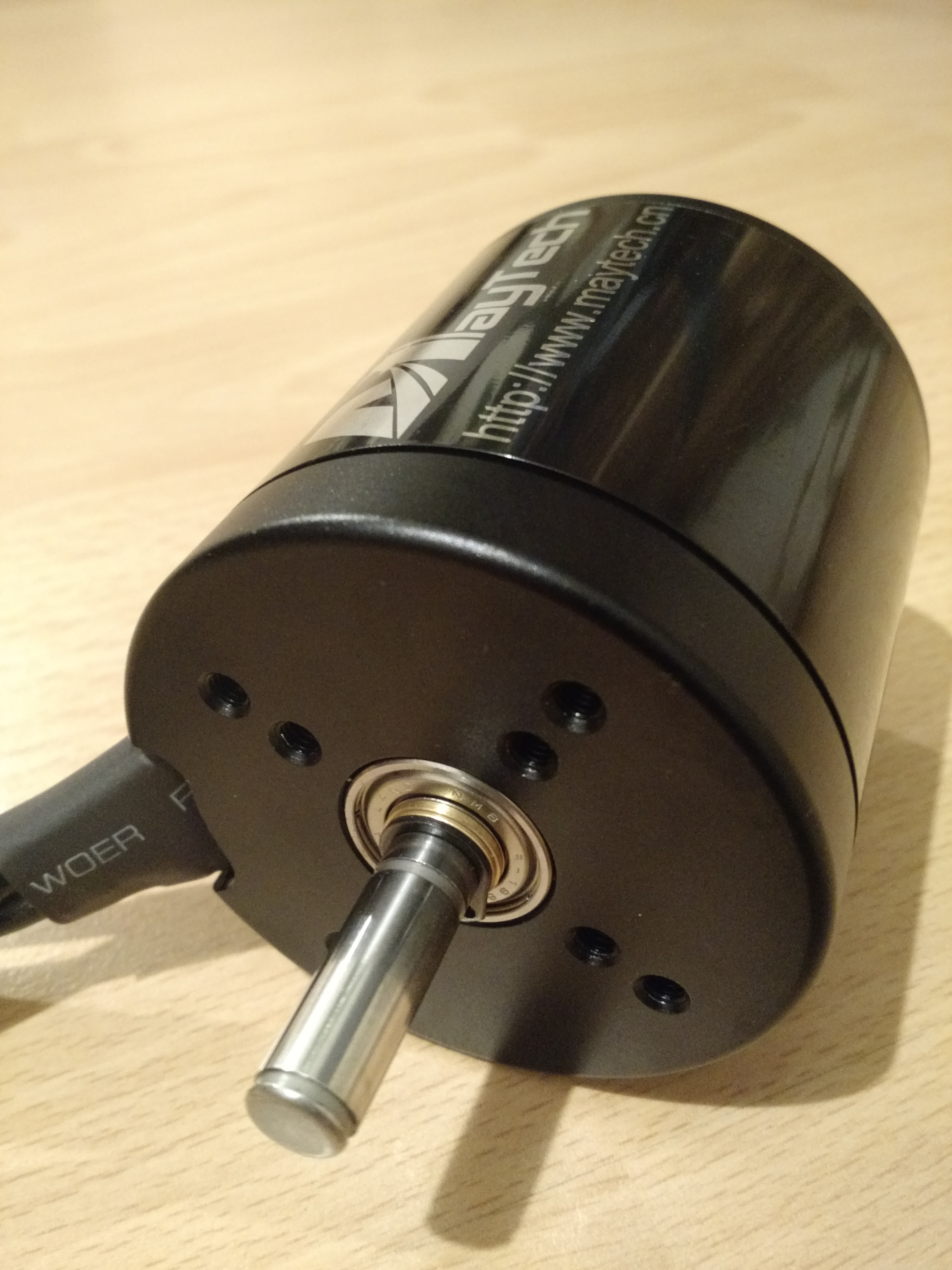
This is the Maytech 6374 motor I will use.
It is sealed and sensored. I missed to take a photo of the keyway.
my built is going really slow. Didn’t expact that…
Could manage a proper motormount for my Kodiak trucks. So i will go with some caliber II for now
And I am still waiting for my focbox.
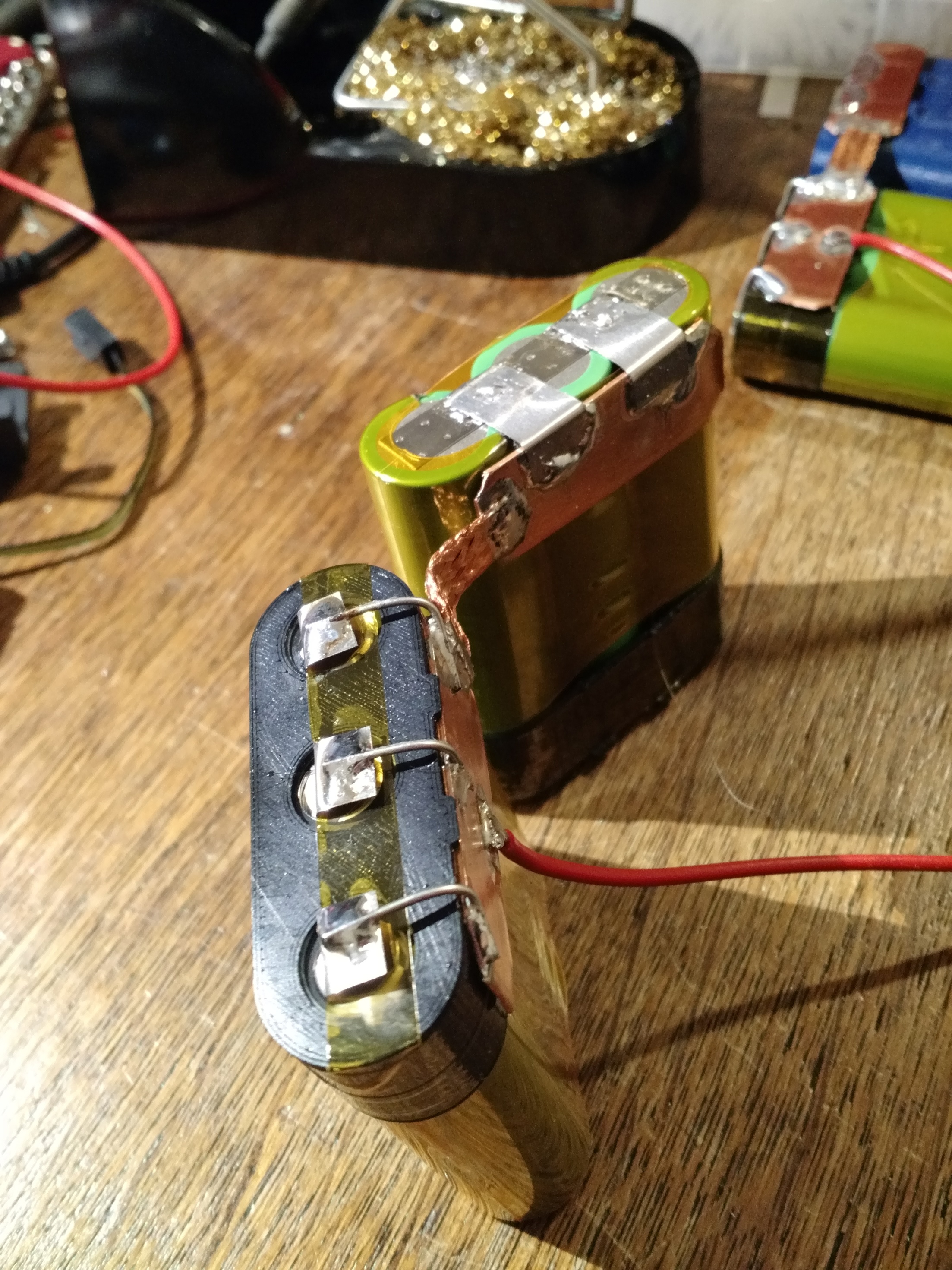
But hear is my first printed part for my 3P battery pack:
It provides single cell level fusing and supports to route the wires for the BMS.
Further i will connect the bus bars with copper mesh wire.
I hope the PLA can withstand the heat?! But I didn’t expact more than 50°C here, right?
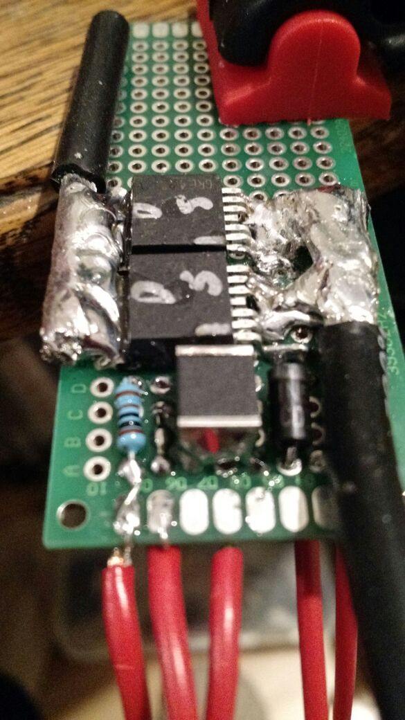
PCB of the Focbox is protectet via 70 Super. To not decrease the heat transfer rate of the FETs they are covered with tape for that process.
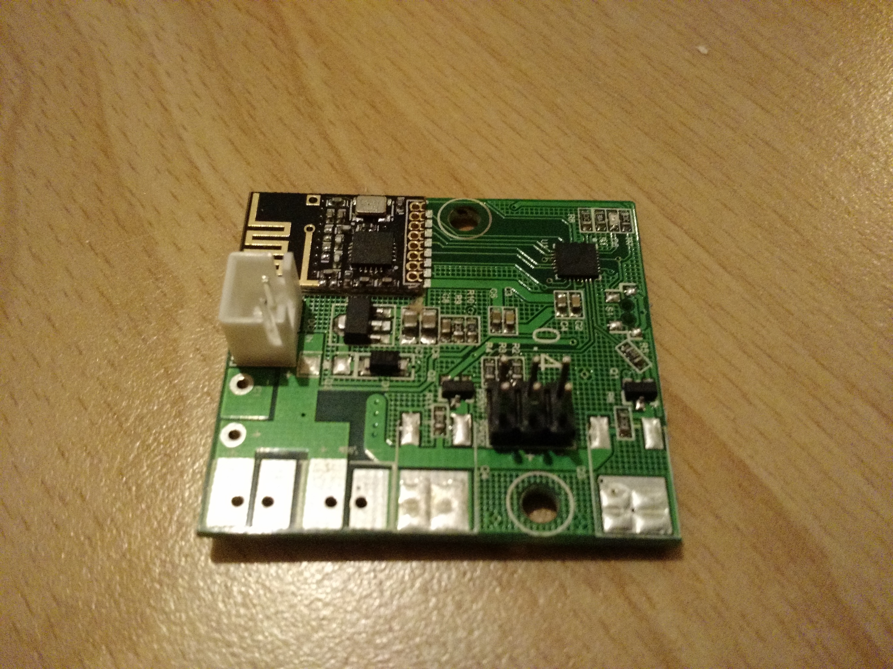
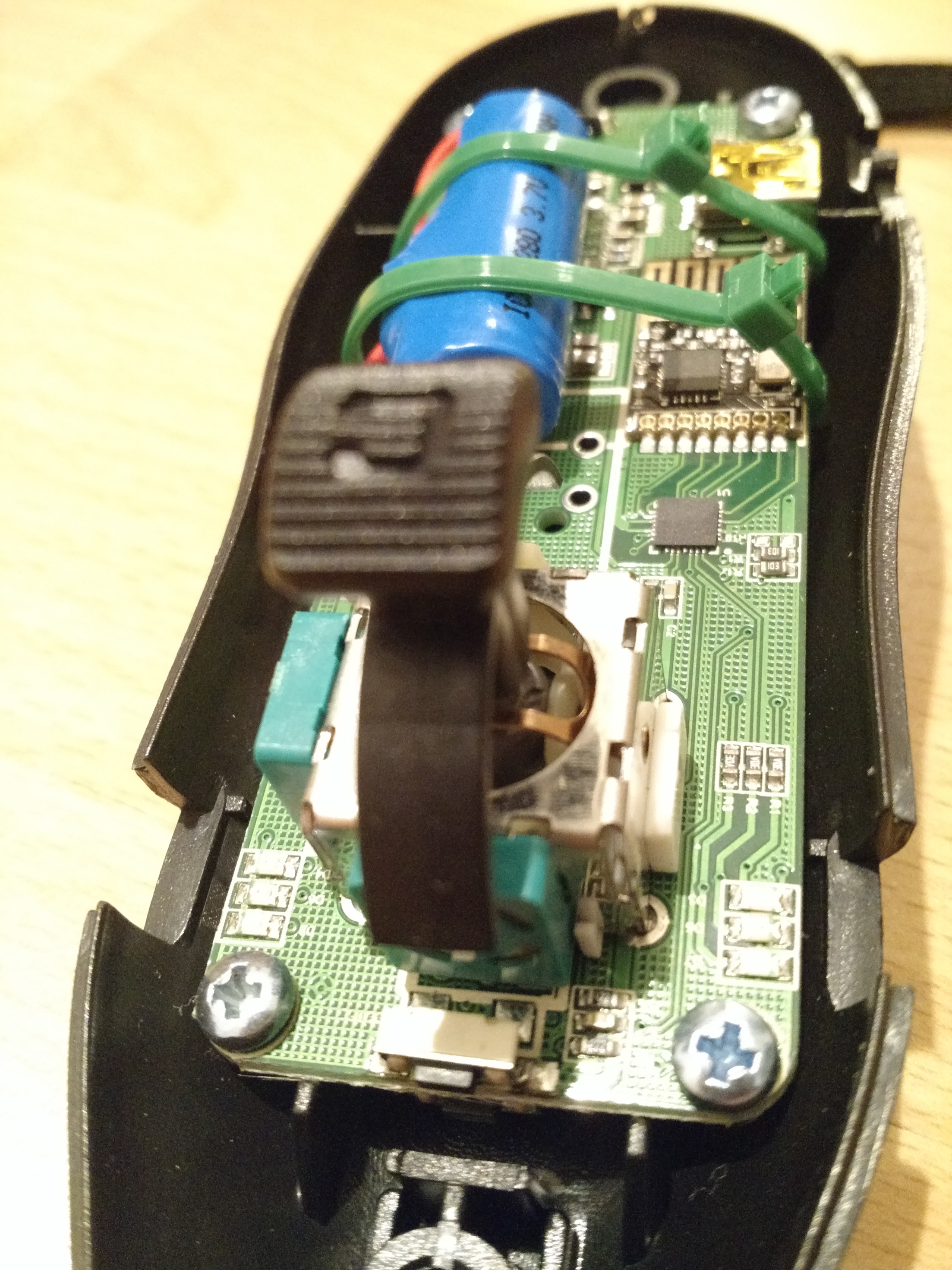
I also covered the PCB of my remote and receiver.
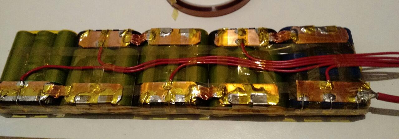
This is my single fuse 10S3P battery pack.
the core is very flexible. With a lot of heatshrink it isn’t that flexible anymore. But it is unlikely to damage the pack by flexing it.
The positve pole has some nickel on it to solder the the fuse on. And it is protected against short circuits to the housing (negative pole)
I have to modify my Tesseract Cantellated to fit 1/2" riser, 90mm Flywheels and 44° Caliber trucks.
Right now I still have wheelsbites.
Or is there any other option? Maybe other bushings?
Man i didn’t expect someone to actually build such a frankenstein charger, i love it!
The rest looks great too, i really like the cell level fusing. Do you think one could get away without using nickel bits on the cells and just soldering the wire directly to them?
yeah, it really looks strange. But it is doing it’s job pretty good :)[/quote]
Sure, you can solder direct to the positive pole.
But i wanted to stress the cells as less as possible. And doing it with this extra nickle you are adding some more clearance between the positive pole and the edge of the housing, which is negative pole respectively your 3D-print case.
what gauge is your cell fuse? It looks pretty beefy, according to this for example, it might take a pretty high current to actually burn off… the biggest problem being that if something goes wonky with a cell, you still might not have the amps/voltage difference to actually get up to that current and burn it off. Nice setup though, even if fuse wires is a tricky business.
At the end I went for caliber II
wasn’t able to create a well aligned mount for my bear kodiaks…
But with the right bushing setup they are not that bad


 And I am still waiting for my focbox.
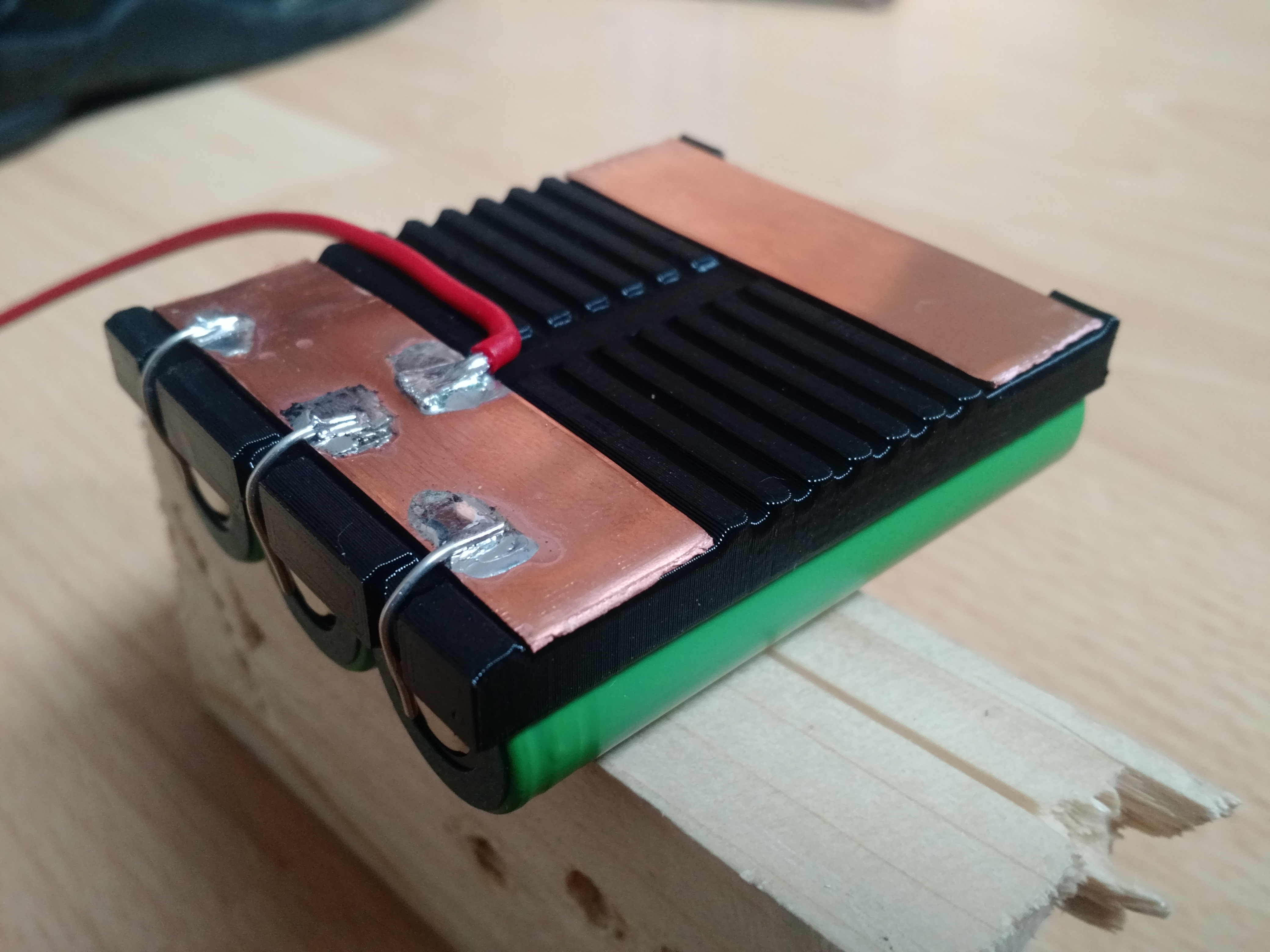


 wasn’t able to create a well aligned mount for my bear kodiaks…
But with the right bushing setup they are not that bad
wasn’t able to create a well aligned mount for my bear kodiaks…
But with the right bushing setup they are not that bad